Electrical plug connector

a technology of electric plugs and connectors, applied in the direction of coupling contact members, fixed connections, coupling device connections, etc., can solve the problems that the electric plugs with blanking-type terminals do not meet the gen2 specification, and achieve the effect of wide thickness, reduced width, and high frequency characteristics

Active Publication Date: 2021-03-25
ADVANCED CONNECTEK INC
View PDF0 Cites 1 Cited by
  • Summary
  • Abstract
  • Description
  • Claims
  • Application Information

AI Technical Summary

Benefits of technology

[0014]In one or some embodiments, the terminals of the signal terminal group are arranged into two rows, the signal terminal group comprises a plurality of high-speed signal terminals and a plurality of low-speed signal terminals.
[0015]According to one or some embodiments of the instant disclosure, the terminals of the power terminal group and the terminals of the signal terminal group are formed as terminals in different types. The power terminal group and the signal terminal group are provided in the same electrical plug connector, such that the electrical plug connector is applicable for transmitting a current having 6 Amps or more and meets the Gen2 specification.
[0016]The thicknesses for different portions of the terminal of the signal terminal group are approximately the same, thereby being suitable for high-speed signal transmission and high frequency characteristics adjustment. The thicknesses for different portions of the terminal of the power terminal group are not the same, and the thickness of the terminal of power terminal group is gradually reduced (the terminal of the power terminal group may have a wider thickness for the second tail portion but have a reduced width for the second contact portion, but embodiments are not limited thereto). The signal terminal group uses the bent-type terminals for meeting the Gen2 specification, and the signal terminal group is served as terminals for signal transmission. The power terminal group uses the blanking-type terminals, and the power terminal group is served as terminals for power transmission. The cross-sectional area of the blanking-type terminal is greater than the cross-sectional area of the bent-type terminal thereby suitable for transmitting a current having 6 Amps or more. The blanking-type terminal has a greater charging speed as compared with the charging speed of the bent-type terminal.
[0017]Detailed description of the characteristics and the advantages of the instant disclosure are shown in the following embodiments. The technical content and the implementation of the instant disclosure should be readily apparent to any person skilled in the art from the detailed description, and the purposes and the advantages of the instant disclosure should be readily understood by any person skilled in the art with reference to content, claims, and drawings in the instant disclosure.

Problems solved by technology

Nevertheless, the electrical connector with the blanking-type terminals does not meet the Gen2 specification.

Method used


Image

  • Electrical plug connector
  • Electrical plug connector
  • Electrical plug connector

Examples


Embodiment Construction

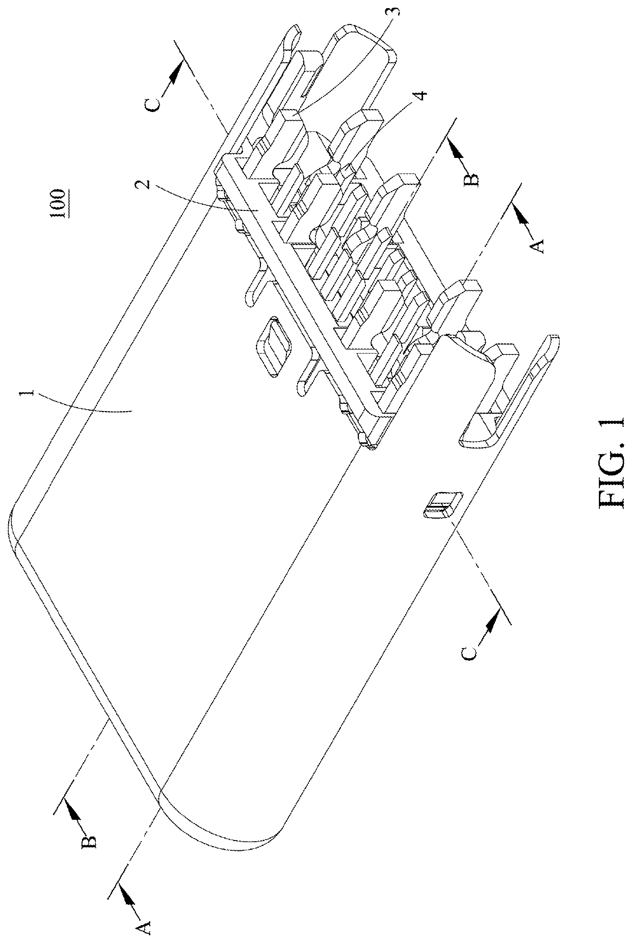
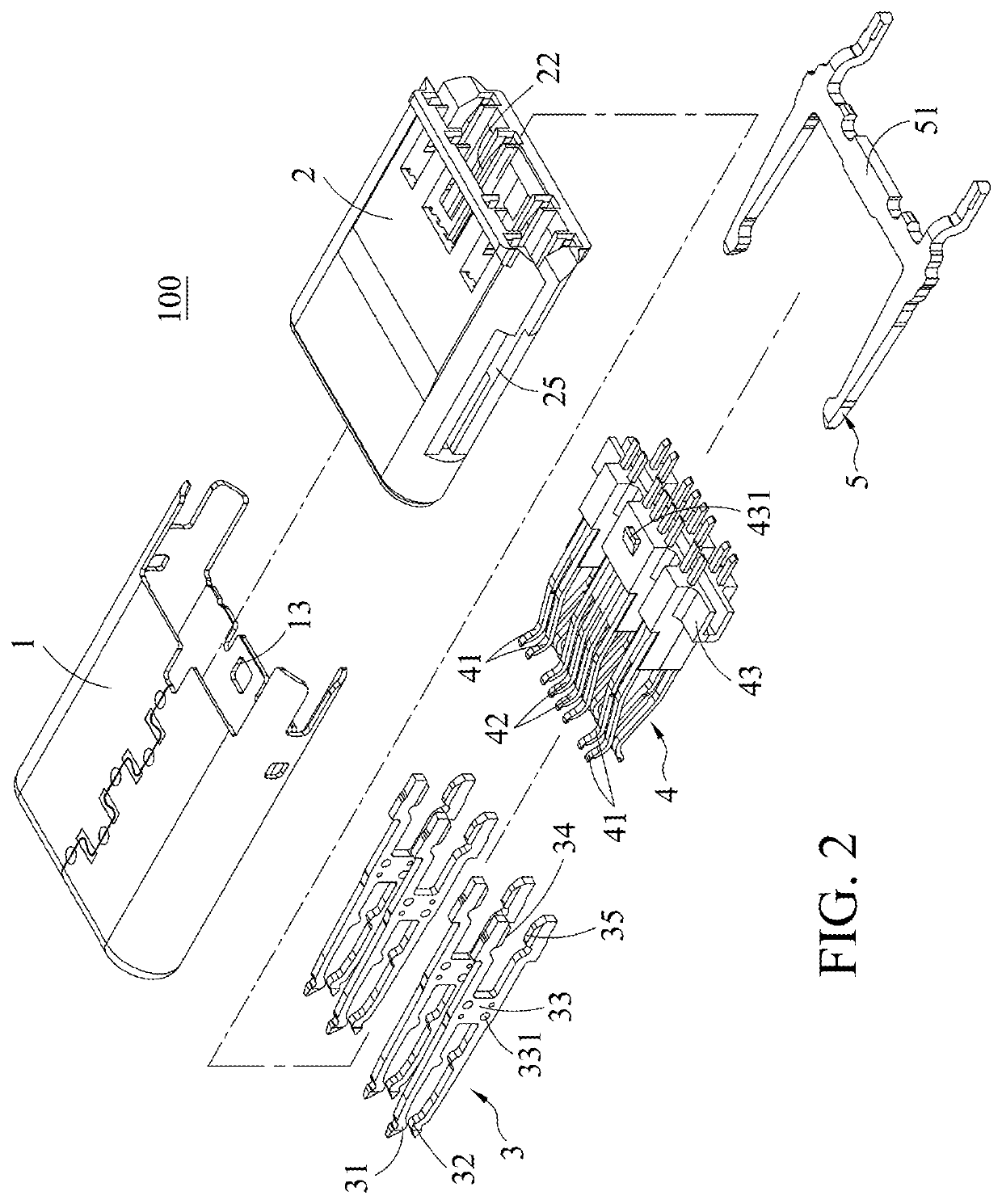
[0032]Please refer to FIGS. 1 and 2. An electrical plug connector 100 according to a first embodiment of the instant disclosure is illustrated. FIG. 1 illustrates a perspective view of the electrical plug connector 100 of the first embodiment. FIG. 2 illustrates an exploded view of the electrical plug connector 100 of the first embodiment. In this embodiment, the electrical plug connector 100 comprises a metallic shell 1, an insulated housing 2, a power terminal group 3, and a signal terminal group 4.

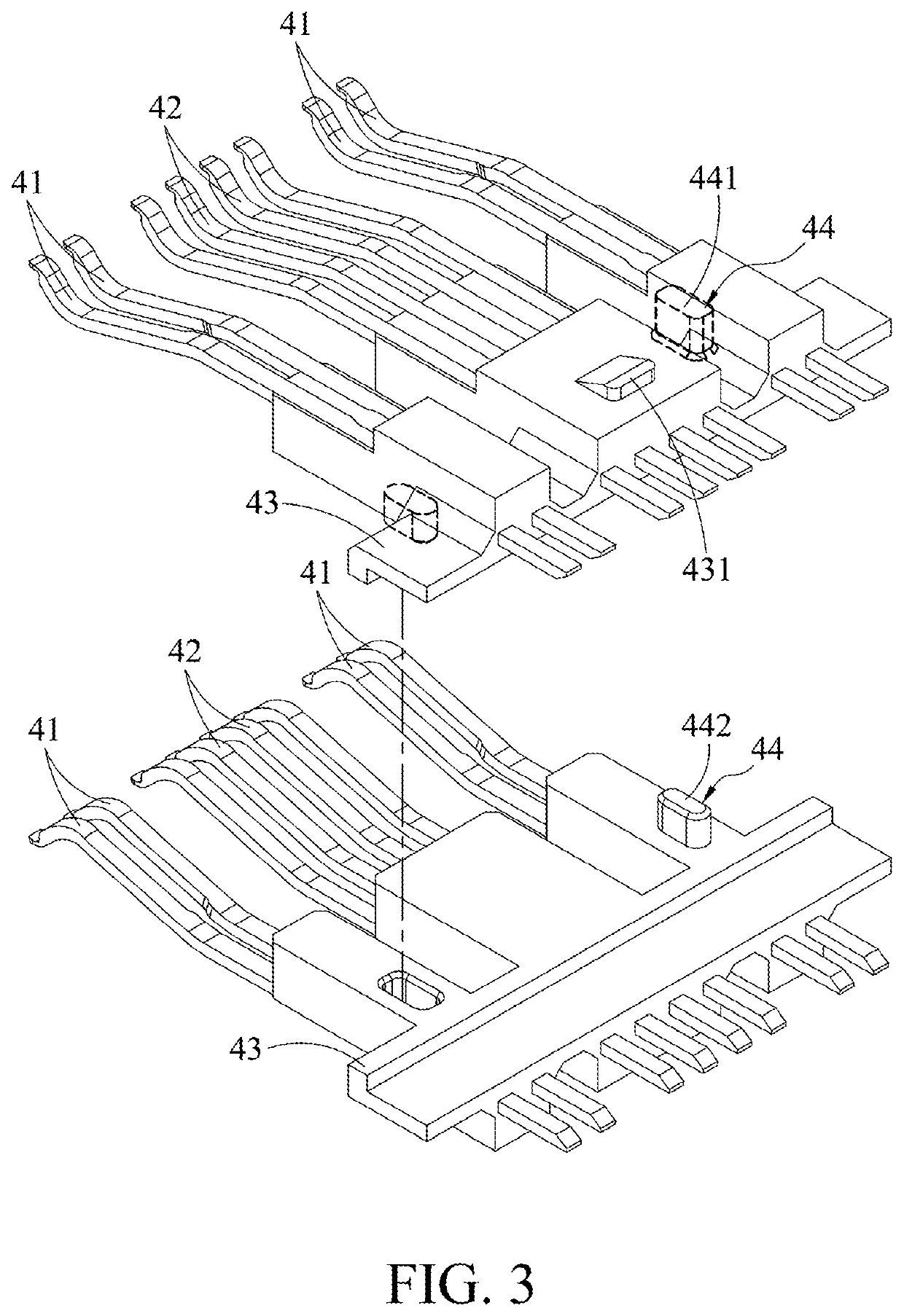
[0033]Please refer to FIGS. 1 to 7. FIG. 3 illustrates an exploded view of the signal terminal group of the electrical plug connector of the first embodiment. FIG. 4 illustrates a top sectional view of the electrical plug connector of the first embodiment. FIG. 5 illustrates a cross-sectional view along line AA shown in FIG. 1. FIG. 6 illustrates a cross-sectional view along line BB shown in FIG. 1. FIG. 7 illustrates a cross-sectional view along line CC shown in FIG. 1.

[0034]In this em...


PUM


Abstract

An electrical plug connector includes a metallic shell, an insulated housing, a power terminal group, and a signal terminal group received in the metallic shell. Each terminal of the power terminal group includes a first contact portion, a second contact portion, and a positioning plate that are formed as a clamp structure. The first contact portion extends from an upper portion of the positioning plate and is above the insertion cavity of the insulated housing. The second contact portion extends from a lower portion of the positioning plate and is below the insertion cavity of the insulated housing. Each terminal of the signal terminal group is side-by-side arranged with the corresponding terminal of the power terminal group. A cross-sectional area of each terminal of the signal terminal group is less than a cross-sectional area of the corresponding terminal of the power terminal group.

Description

CROSS-REFERENCE TO RELATED APPLICATION[0001]This non-provisional application claims priority under 35 U.S.C. § 119(e) to U.S. Provisional Patent Application No. 62 / 902,687, filed on Sep. 19, 2019, the entire contents of which are hereby incorporated by reference.FIELD OF THE INVENTION[0002]The instant disclosure relates to an electrical connector, and more particular to an electrical plug connector.BACKGROUND[0003]The appearance, the structure, the contact ways of terminals, the number of terminals, the pitches between terminals (the distances between the terminals), and the pin assignment of terminals of a USB type-C electrical connector known to the inventor(s) are totally different from those of a USB electrical connector known to the inventor(s).[0004]A USB type-C electrical receptacle connector known to the inventor(s) includes a plastic core, upper and lower plug terminals held on the plastic core, an outer iron shell circularly enclosing the plastic core, hook structures at t...

Claims


Application Information

Patent Timeline
Patent Type & Authority Applications(United States)
IPC IPC(8): H01R13/424H01R13/506H01R24/60
CPCH01R13/424H01R24/60H01R13/506H01R12/722H01R13/02H01R12/57H01R13/646H01R13/112H01R12/7088H01R13/405H01R13/41H01R13/26H01R13/42H01R13/6271H01R13/629H01R13/6583H01R2107/00H01R13/11
Inventor CHANG, MING-YUNGCHEN, MAO-SHENG
Owner ADVANCED CONNECTEK INC
Why Eureka
Try Eureka