Electron gun and manufacturing method therefor

a manufacturing method and technology of electron guns, applied in the field of electron guns, can solve the problems of unfavorable electron beam forming, and disturbance of electron trajectory, and achieve the effect of preventing the production of dark curren

Active Publication Date: 2021-04-29
NEW JAPAN RADIO CORP
View PDF0 Cites 0 Cited by
  • Summary
  • Abstract
  • Description
  • Claims
  • Application Information

AI Technical Summary

Benefits of technology

[0012]The above-mentioned another aspect of the present disclosure in which the opening edge of the through hole of the cathode is chamfered to form the C chamfer or the R chamfer makes it possible to eliminate emission of electrons from the opening edge of the through hole of the cathode and to prevent production of dark current.

Problems solved by technology

However, there is a problem that, even with the method disclosed in CN202633200U, with a hollow cathode, electrons emitted from the inner surface of a through hole being formed in a cathode can cause the trajectory of electrons to be disturbed, electron beam forming to be impaired, or unnecessary leakage current called dark current to be produced, the leakage current flowing in the anode direction from the cathode.
Moreover, when an emitter material scattering due to evaporation or sputtering attaches in the through hole being formed in the cathode, electron emission occurs from the above-mentioned emitter material, similarly causing the trajectory of electrons to be disturbed, electron beam forming to be impaired, or dark current to be produced.

Method used


Image

  • Electron gun and manufacturing method therefor
  • Electron gun and manufacturing method therefor
  • Electron gun and manufacturing method therefor

Examples


embodiment 1

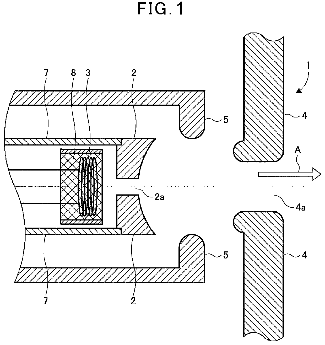
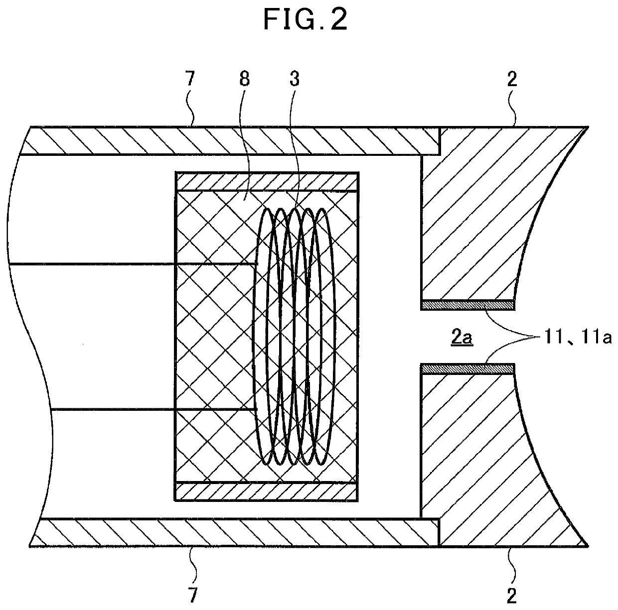
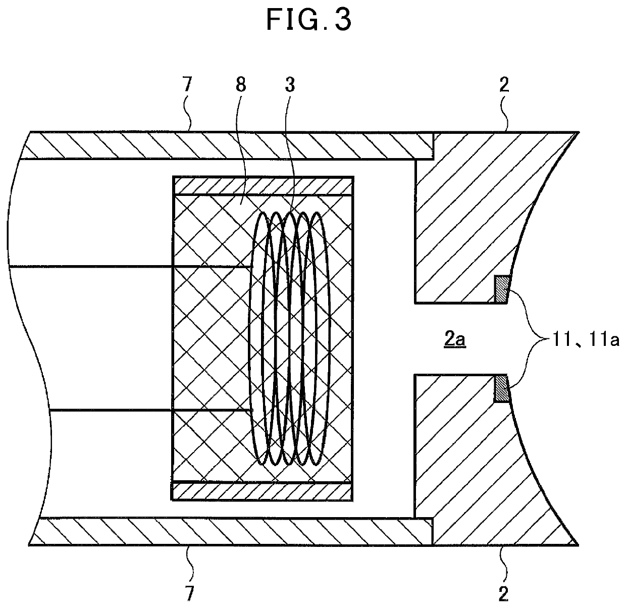
[0045]According to Embodiment 1, a metal layer 11a is provided as a no-emitting layer 11 on an opening edge on the electron emitting surface side of a through hole 2a or on an inner surface of the through hole 2a of a cathode 2. FIGS. 2 to 4 are cross-sectional views showing specific modes of an electron gun 1 according to Embodiment 1 with the cathode 2 being particularly enlarged. In other words, the metal layer 11a being the no-emitting layer 11 fills or covers a pore or convex-concavity being present in the opening edge on the electron emitting surface side of the through hole 2a or in the inner surface of the through hole 2a of the cathode 2 to prevent the electron emission substance from being exposed onto the surface, and as a result, prevents electron emission from this surface.

[0046]The electron gun 1 shown in FIG. 2 is the electron gun comprising the cathode 2 having the electron emitting surface and whose planar shape is circular; the heater 3 to increase the temperature ...

embodiment 2

[0056]According to Embodiment 2, as the no-emitting layer 11a metal layer in which a metal base body is melted and solidified 11b, in which the metal base body makes up a cathode 2, is provided in an opening edge on an electron emitting surface side of the through hole 2a or in an inner surface of the through hole 2a of the cathode 2. FIGS. 5 and 6 are cross-sectional views showing specific modes of an electron gun 1 according to Embodiment 2 with the cathode 2 being particularly enlarged. In other words, the metal layer in which a metal base body is melted and solidified 11b being the no-emitting layer 11 closes a pore being present in the opening edge on the electron emitting surface side of the through hole 2a or in the inner surface of the through hole 2a of the cathode 2 to prevent the electron emission substance from being exposed onto the surface, and as a result, prevents electron emission from this surface.

[0057]The electron gun 1 shown in FIG. 5 is the electron gun compris...

embodiment 3

[0063]According to Embodiment 3, a layer consisting of only a porous metal base body 11c in which the metal base body makes up a cathode 2 is provided as a no-emitting layer 11 in an opening edge on an electron emitting surface side of a through hole 2a or in an inner surface of the through hole 2a of the cathode 2. FIGS. 7 and 8 are cross-sectional views of specific modes of an electron gun 1 according to Embodiment 3 with the cathode 2 being particularly enlarged.

[0064]The electron gun 1 shown in FIG. 7 is the electron gun comprising the cathode 2 having the electron emitting surface and whose planar shape is circular and comprising a porous metal base body and an electron emission substance with which a pore of the porous metal base body is impregnated; and a heater 3 to increase the temperature of the cathode 2; and an anode 4 to apply a positive electric potential relative to the cathode 2 to extract electrons in the predetermined direction (see FIG. 1), wherein the through hol...


PUM

PropertyMeasurementUnit
diameteraaaaaaaaaa
outer diameteraaaaaaaaaa

Abstract

An electron gun comprising a cathode having an electron emitting surface and whose planar shape is circular, a heater to increase the temperature of the cathode, and an anode to apply a positive electric potential relative to the cathode to extract electrons in a predetermined direction is provided. The cathode comprises a through hole at a central portion thereof along a central axis of the cathode, and either the cathode comprises a no-emitting layer at at least one of an opening edge on the electron emitting surface side of the through hole and an inner surface of the through hole, or the opening edge on the electron emitting surface side of the through hole is a chamfered C surface or a chamfered R surface.

Description

CROSS-REFERENCE TO RELATED APPLICATIONS[0001]The present application claims priority to Japanese Patent Application No. 2019-194912, filed Oct. 28, 2019, the content of which are incorporated herein by reference in its entirety.TECHNICAL FIELD[0002]The present disclosure relates to an electron gun, and particularly relates to an electron gun to supply electrons to operate an electron beam generating apparatus, Linac (a linear accelerator), TWT (a traveling wave tube), and Klystron and to a manufacturing method for the electron gun.BACKGROUND OF THE INVENTION[0003]In an electron beam generating apparatus, Linac, TWT, and Klystron as applications for using electron beams, as shown in FIG. 18, an electron gun 101 to emit thermions by using a heater 105 to heat a cathode 102 in which a thermionic emission substance is splayed onto, coated onto, or impregnated into a metal base body is provided. The related-art electron gun 101 emits electrons in a predetermined orientation and, moreover...

Claims


Application Information

Patent Timeline
Patent Type & Authority Applications(United States)
IPC IPC(8): H01J29/48H01J29/04H01J9/04
CPCH01J29/484H01J29/62H01J9/04H01J29/04H01J29/48H01J37/06H01J9/00H01J3/027H01J1/025H01J2201/02H01J23/05H01J23/065H01J25/10H01J25/34
Inventor KIMURA, TORUISEKI, MISAOOBATA, HIDEYUKI
Owner NEW JAPAN RADIO CORP
Why Eureka
Try Eureka