
Substrate treatment apparatus

Pending Publication Date: 2021-04-29
SEMES CO LTD
View PDF0 Cites 0 Cited by
  • Summary
  • Abstract
  • Description
  • Claims
  • Application Information

AI Technical Summary

Benefits of technology

The present invention provides a substrate processing apparatus that can reliably operate and prevent breakage of a substrate. It also includes a chemical fluid recovery unit that can be oriented horizontally to easily introduce various chemical fluids without mixing them. This allows for the recovered chemical fluids to be reused.

Problems solved by technology

Contaminants such as particles of organic materials and metallic materials on the surface of a substrate have a significantly negative effect on the characteristics and production yield of semiconductor devices formed on the substrate.
The pneumatic cylinders mounted to the recovery device have a problem in that an internal pressure difference occurs between the pneumatic cylinders in a standby state prior to the operation of the recovery unit.
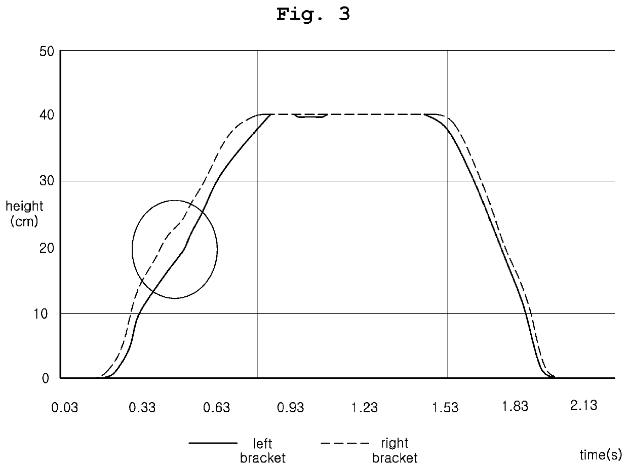
The pressure difference results in a height difference between the pneumatic cylinders by which the recovery unit is supported.
In this case, the recovery unit is likely to tilt, thereby exerting a transverse load to the cylinders.
Because of this, wear easily occurs in the sealing ring installed on the periphery of the piston, and air leaks from the bottom of the cylinder.
Consequently, there is a possibility that the lifting units malfunction.
In addition, when the recovery unit tilts excessively, a chemical fluid cannot be introduced into the target compartment in the recovery unit and may be erroneously introduced into a non-target compartment.
The erroneously introduced chemical fluid will be mixed with another chemical fluid stored in the non-target compartment and thus the recovered chemical fluid cannot be reused.

Method used


Image

  • Substrate treatment apparatus
  • Substrate treatment apparatus
  • Substrate treatment apparatus

Examples


first embodiment

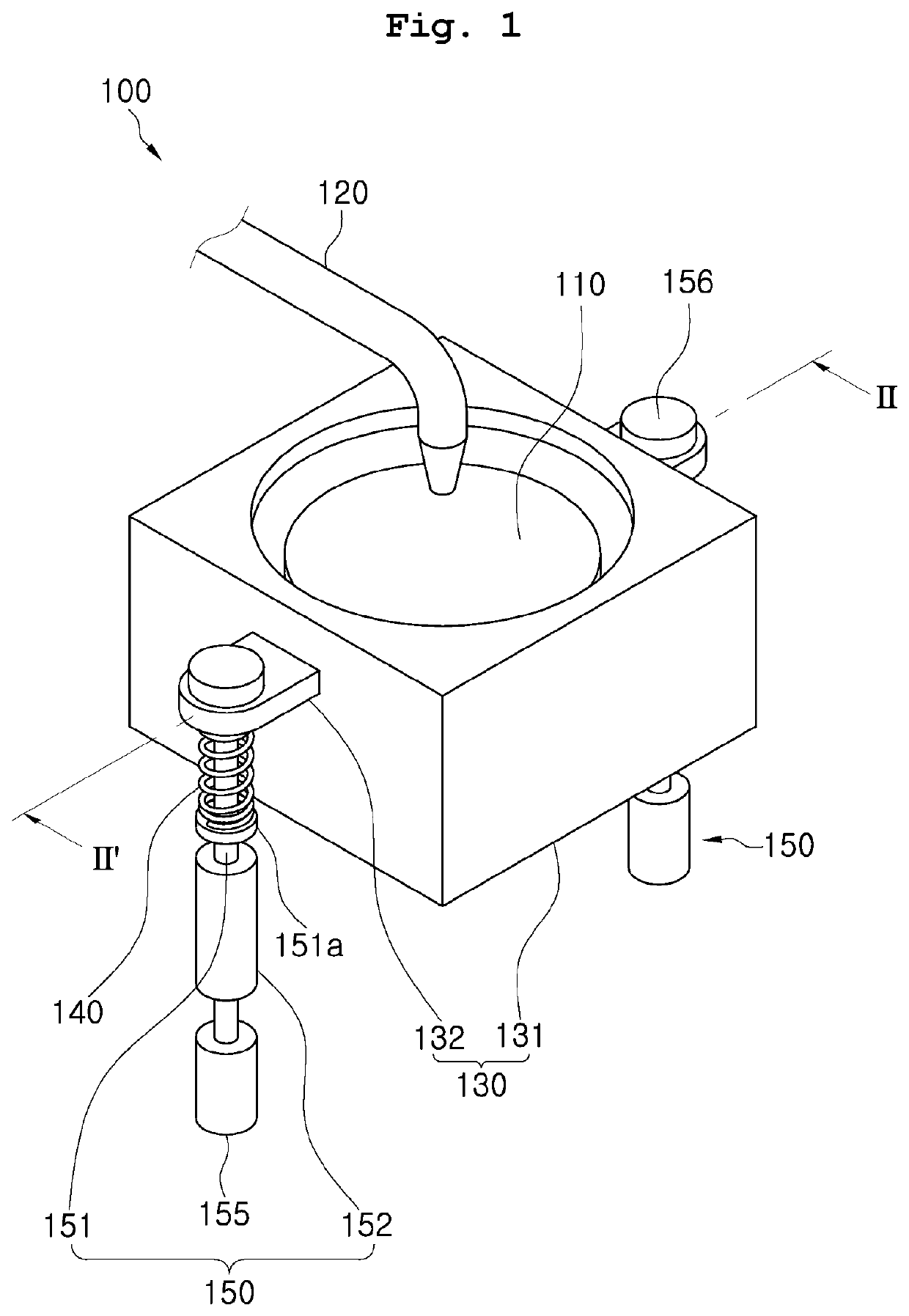
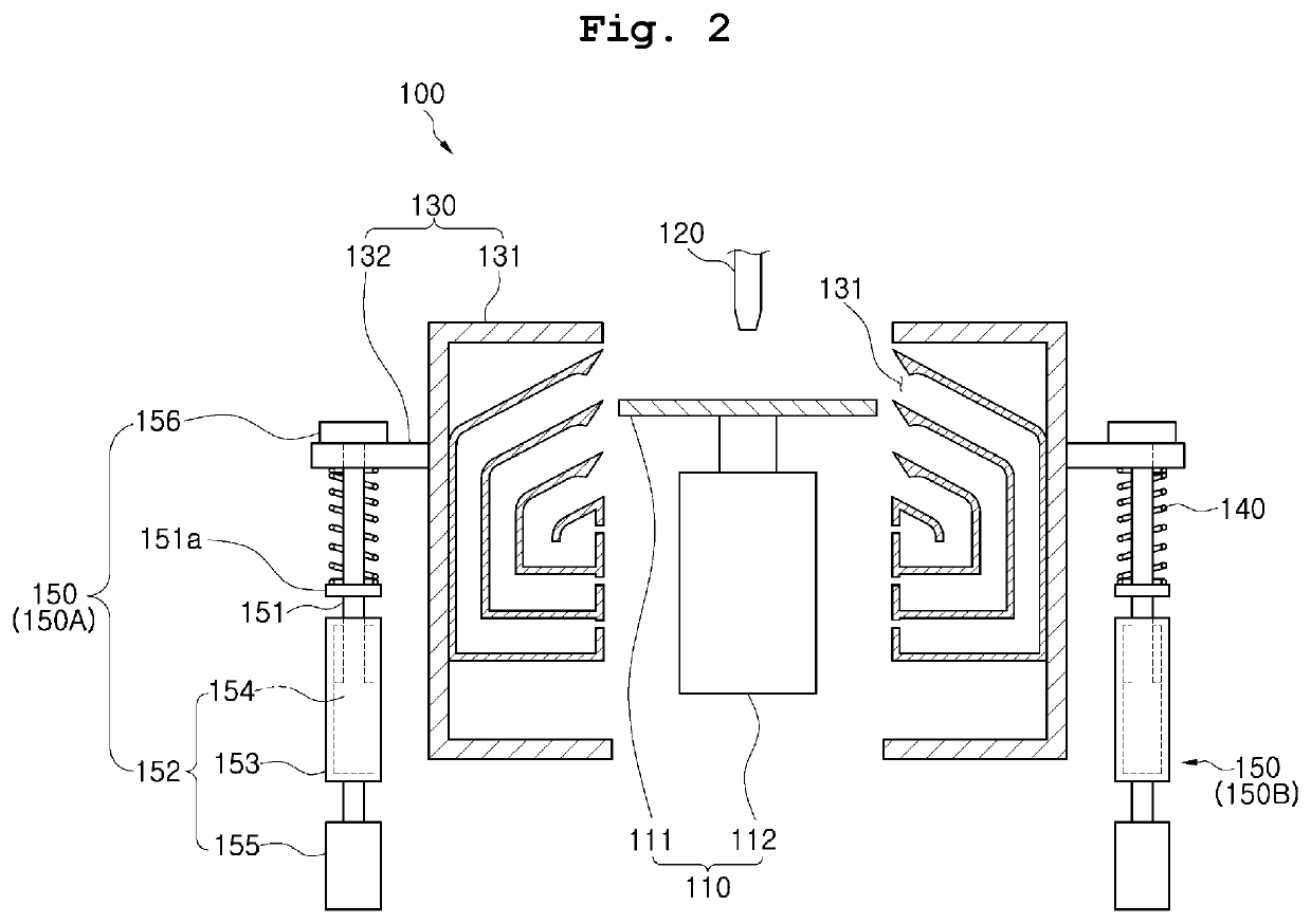
[0041]Referring to FIGS. 1 to 2, according to the present invention, a substrate processing apparatus 100 includes a rotation unit 110, a chemical ejection unit 120, a chemical recovery unit 130, a lifting unit 150, and a position correction member 140.

[0042]The rotation unit 110 supports and rotates a substrate (not illustrated). The rotation unit 110 includes, for example, a support plate 111 and a rotation motor 112.

[0043]The support plate 111 supports a substrate. The support plate 111 is larger in size than the substrate. When the substrate is a circular wafer, the support plate 111 may be a circular plate having a larger diameter than the wafer.

[0044]The rotation motor 112 is positioned below the support plate 111. The rotation motor 112 rotates the support plate 111.

[0045]When the substrate is seated on the support plate 111, the support plate 111 is rotated and the substrate on the support plate is accordingly rotated. When a chemical fluid is ejected to the center of the su...

second embodiment

[0090]Referring to FIG. 7, in a substrate processing apparatus 200 according to the present invention, two position correction members 140A and 140B are engaged with one lifting unit.

[0091]Of the two position correction members 140A and 140B, one position correction member 140A is installed to surround a movable member 151 and is positioned between a driving force generation member 152 and a bracket portion 132. Of the two position correction members 140A and 140B, the other position correction member 140B is disposed between the retaining member 156 and the bracket portion 132.

[0092]In the substrate processing apparatus 200 according to the second embodiment of the present invention, an upper side and a lower side of the bracket portion 132 are elastically supported by the position correction member 140. Therefore, the chemical recovery unit 130 of the substrate processing apparatus 200 can be moved up and down more flexibly compared to the substrate processing apparatus 100 accord...

third embodiment

[0093]Referring to FIGS. 8 and 9, a substrate processing apparatus 300 according to the present invention additionally includes stress prevention members 360.

[0094]The stress prevention member 360 is installed such that an end portion of the movable member 151 passes through the stress prevention member 360. The stress prevention member 360 is positioned between the retaining member 156 and the bracket portion 132.

[0095]The stress prevention member 360 has, for example, a spherical shape. Accordingly, the stress prevention member 360 is in spot contact with the retaining member 156 and is in spot contact with the bracket portion 132.

[0096]When the chemical recovery unit 130 is about to tilt excessively due to an external impact or certain failure, the stress prevention member 360 prevents the bracket portion 132 and the retaining member 156 from coming into contact with each other. Therefore, it is possible to prevent the bracket portion 132 and the retaining member 156 from being s...


PUM


Abstract

A substrate processing apparatus includes a rotation unit supporting and rotating a substrate, a chemical ejection unit ejecting a chemical fluid toward the rotation unit, a chemical recovery unit disposed close to the rotation unit and collecting a chemical fluid scattered from the rotation unit, a first lifting unit coupled to the chemical recovery unit and moving upward and downward the chemical recovery unit relative to the rotation unit, and a first position correction member allowing the chemical recovery unit to be elastically supported by the first lifting unit and changing a relative position of the chemical recovery unit with respect to the lifting unit.

Description

CROSS REFERENCE TO RELATED APPLICATION[0001]The present application claims priority to Korean Patent Application No. 10-2019-0134574, filed Oct. 28, 2019, the entire contents of which are herein incorporated by reference.BACKGROUND OF THE INVENTION1. Field of the Invention[0002]The present invention relates to a substrate processing apparatus and, more particularly, to a substrate processing apparatus, a substrate processing equipment, and a substrate processing method that are suitably used to manufacture semiconductor devices.2. Description of the Related Art[0003]The miniaturization of circuit patterns has rapidly progressed with increases in density, integration, and performance of semiconductor devices. Contaminants such as particles of organic materials and metallic materials on the surface of a substrate have a significantly negative effect on the characteristics and production yield of semiconductor devices formed on the substrate. Therefore, a cleaning process of removing v...

Claims


Application Information

Patent Timeline
IPC IPC(8): H01L21/67H01L21/687
CPCH01L21/6715H01L21/68764H01L21/68742H01L21/67023H01L21/67051H01L21/67259
Inventor PARK, IN HWANGKIM, SUNG PILKIM, KUK SAENGKIM, KYUNG MIN
Owner SEMES CO LTD
Learn More