Input Circuit for a Power Supply

Pending Publication Date: 2021-04-29
SIEMENS AG
View PDF1 Cites 0 Cited by
  • Summary
  • Abstract
  • Description
  • Claims
  • Application Information

AI Technical Summary

Benefits of technology

[0015]In view of the foregoing, it is therefore an object of the invention to provide an input circuit for a power supply, which

Problems solved by technology

In normal switching mode of the switch element, the predefined breakthrough voltage does not occur, because otherwise

Method used


Image

  • Input Circuit for a Power Supply
  • Input Circuit for a Power Supply
  • Input Circuit for a Power Supply

Examples


Example

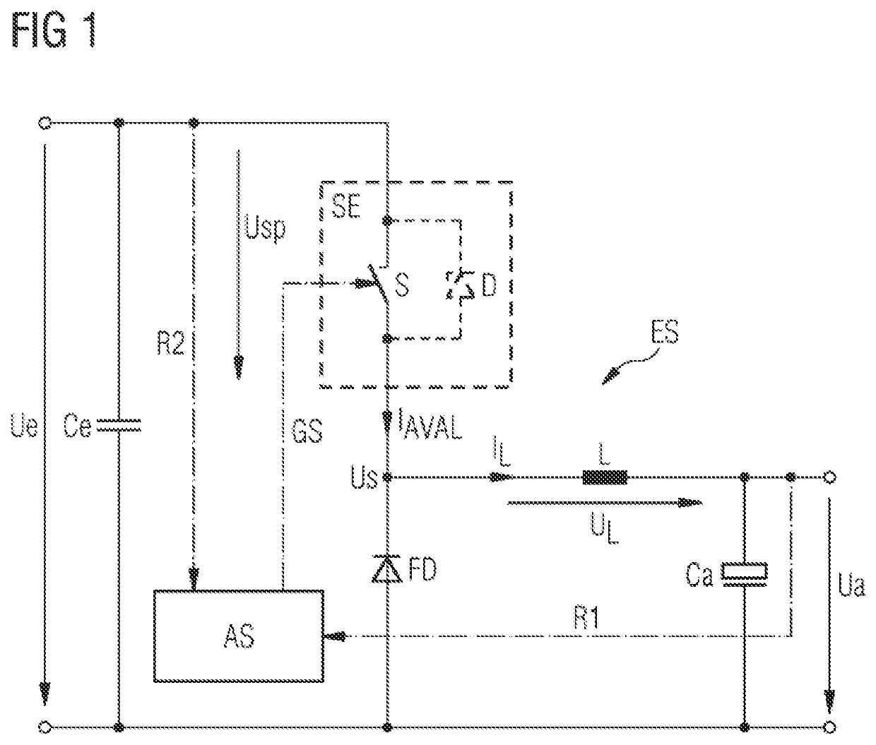
[0041]FIG. 1 schematically shows an exemplary embodiment of the inventive input circuit ES for a power supply, which can be linked, for example, to a single or multiphase, especially at least two- or three-phase, power supply system. The input circuit ES has at least a circuit topology of a buck converter. As an alternative, however, the input circuit can also be formed as a combination of buck converter and boost converter. Arranged on an input side of the input circuit ES is an input capacitance Ce, at which a mostly unstabilized or unregulated input voltage Ue is present. The input voltage Ue can, for example, be made available by an input stage of the power supply through which a link to the power supply system is made.

[0042]The input capacitance Ce in this case has the function of the input circuit ES for example, which operates with a much higher frequency than the system frequency of the input voltage Ue (e.g., a factor of 1000), to make the high-frequency pulse currents avai...


PUM


Abstract

An input circuit for a power supply includes an input voltage that is converted into an output voltage via periodic switching of a switch between conductive/blocked states, wherein current that charges a capacitance and supplies output voltage flows through an inductor at least during switching of the switch, and is absorbed by an active switch unit when the switch is in the blocked state and is permitted through the switch in the blocked state, upon exceeding a predefined breakdown voltage at the switch, such that during an overvoltage at the input circuit, the switch is switched into the blocked state, and current flow that then occurs is relayable into the inductor and the active switch unit is deactivatable, the switch and inductor being dimensioned such that, during an overvoltage, an “avalanche energy” occurs at the switch, upon which the switch withstands the current flowing through the inductor during the over-voltage.

Description

CROSS-REFERENCE TO RELATED APPLICATIONS[0001]This is a U.S. national stage of application No. PCT / EP2019 / 065826 filed 17 Jun. 2019. Priority is claimed on European Application No. 18178782.1 filed 20 Jun. 2018, the content of which is incorporated herein by reference in its entirety.BACKGROUND OF THE INVENTION1. Field of the Invention[0002]The subject matter of the invention generally relates to the field of electrical engineering and, more particularly, to the area of power electronics as well as to power electronics circuits and, more specifically, relates to an input circuit for a power supply, where an input voltage of the input circuit is converted into an output voltage of the input circuit by periodically switching a switch element between a conductive and a blocked state, where an inductance arranged in series with the switching element has a current flowing through it at least partially during a switching period, where this current charges an output-side capacitance, by whi...

Claims


Application Information

Patent Timeline
IPC IPC(8): H02M3/156H02H7/12H02M1/32
CPCH02M3/156H02M1/32H02H7/1213H02M1/348
Inventor ROTHMAYER, THOMASSCHWELGERT, HARALD
Owner SIEMENS AG
Why Eureka
Try Eureka