Distortion mitigation in directed energy deposition

a technology of directed energy deposition and distortion mitigation, which is applied in the direction of manufacturing tools, soldering devices, auxillary welding devices, etc., can solve the problems of high material waste of expensive titanium metal that is often machined away, large lead time associated with the fabrication of metal parts, and inevitable build-up of complex thermally induced residual stress and distortion during layer upon layer fabrication. , to reduce or minimize residual stress or distortion, the effect of improving material quality

Pending Publication Date: 2021-05-27
NORSK TITANIUM
View PDF9 Cites 2 Cited by
  • Summary
  • Abstract
  • Description
  • Claims
  • Application Information

AI Technical Summary

Benefits of technology

[0014]Accordingly, embodiments provided herein are directed to production of workpieces having reduced or minimized residual stress, or distortion, or both using additive manufacturing processes that substantially obviates one or more of the problems due to limitations and disadvantages of the related art. As embodied and broadly described, provided are devices, systems and methods to reduce or minimize residu...

Problems solved by technology

These techniques have a disadvantage of high material waste of the expensive titanium metal that often is machined away, and large lead times associated with the fabrication of the metal part.
The incompatible elastic and/or plastic strain field involved in DED of metals, caused by non-uniform thermal loading near the processing region, leads to an inevitable build-up of complex thermally induced residual stresses and distortion during layer upon layer fabrication.
The formation and relaxation of residual stresses during DED of metals can cause unwanted plastic deformation in areas bordering the processing zone, which can carry over to the as-deposited preform.
The residual stress locked in the as-deposited DED preform can lead to permanent loss of tolerance in the workpiece, because the workpiece self-equilibrates the residual stress field that still exists in the structure when released from the clamping fixture platform or jig.
Adverse distributions of residual stress in engineered components also can lead to unexpected or premature failure, i.e. in areas of high tensile stresses prone to fracture and fatigue.
The resulting thermal stress can cause a non-uniform distribution of irreversible material deformation, and some of this deformation can remain after the material has cooled, resulting in an internal and completely self-equilibrating stress field in the workpiece.
This self-equilibration can result in metal structures that are geometrically out of tolerance due to distortion or warping.
The heat generated can cause thermal dilation of material, accompanied by a gradual decrease in yield strength.
Because molten material will not support a load, stress underneath the thermal source is close to zero.
For the balancing compressive forces,...

Method used


Image

  • Distortion mitigation in directed energy deposition
  • Distortion mitigation in directed energy deposition
  • Distortion mitigation in directed energy deposition

Examples


example 1

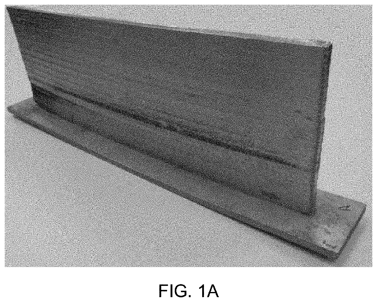
[0213]A first base plate substrate having dimensions (L×W×T) of 635 mm×190 mm×9.5 mm and made of Ti-6Al-4V was used as a first test substrate to determine deflection without residual stress mitigation. The substrate was clamped to a jig or welding table and a workpiece was produced on the workpiece using a first PTA torch to pre-heat the base material, and a second PTA torch to melt a Ti-6Al-4V wire to form molten metal that was deposited onto the pre-heated base material. The speed of deposition was between 7.5 and 10 mm / s and inert gas was used to direct a cooling gas at high flow rate to impinge upon the as-solidified material adjacent to a liquid-solid boundary of the liquid molten pool. After the deposition was complete, the component was cooled and removed from the jig, and the substrate was examined for deformations.

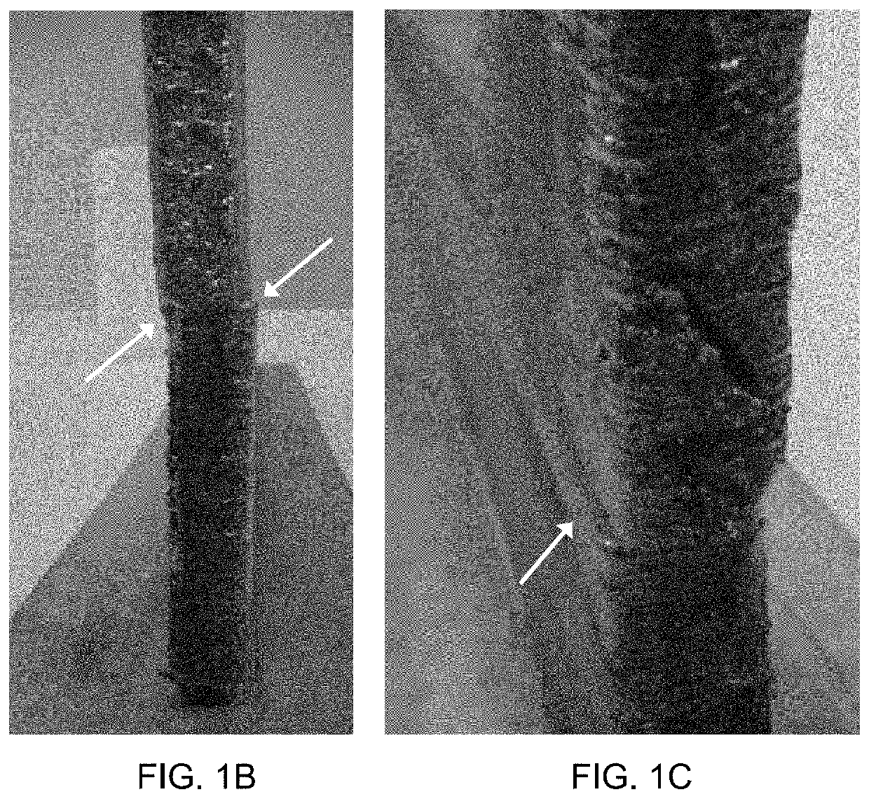
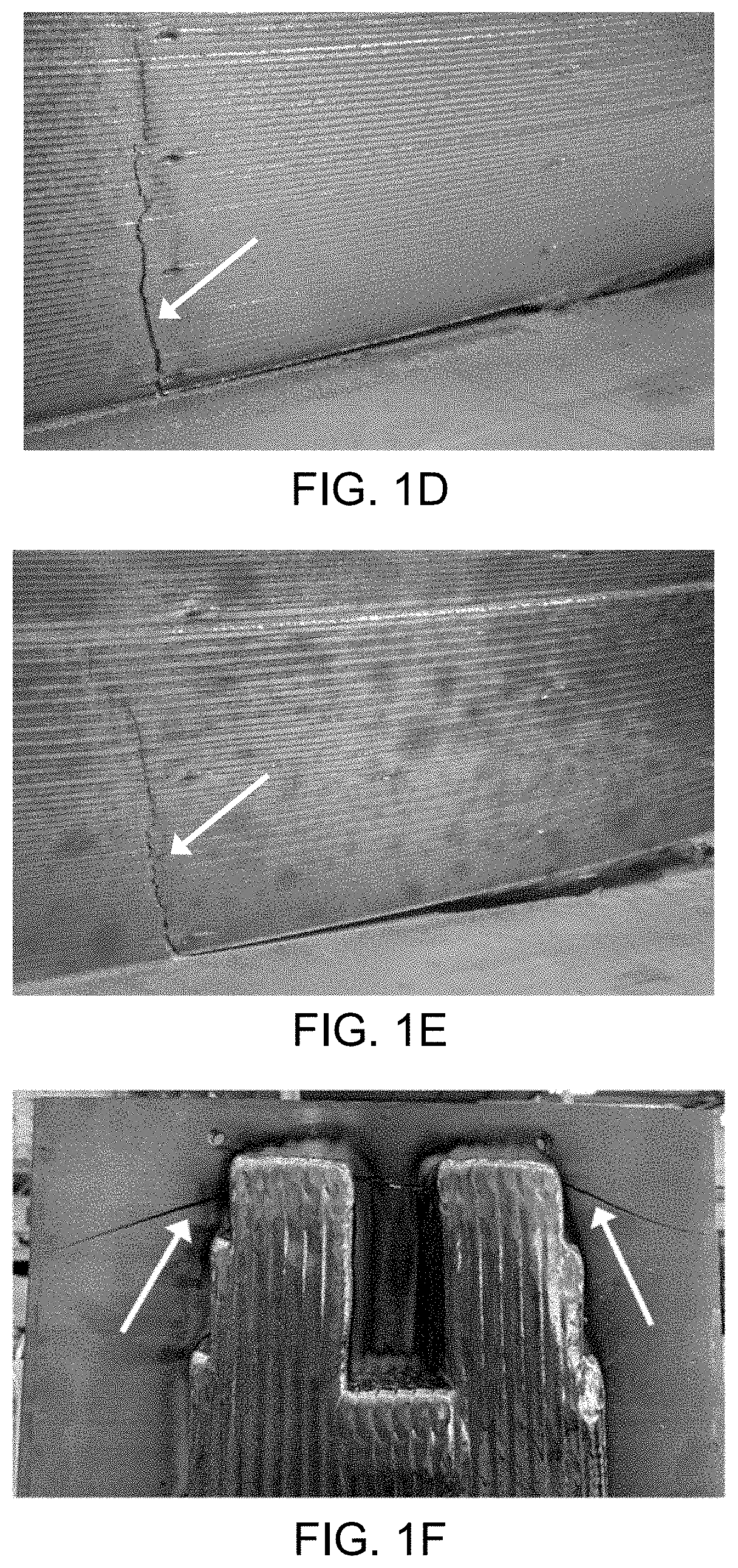
[0214]Distortion was apparent at the short edges of the substrate, which bowed upward compared to the flatness profile of the substrate prior to deposition. The d...


PUM

PropertyMeasurementUnit
Temperatureaaaaaaaaaa

Abstract

Provided are a curved clamping mold and systems and methods using the curved clamping mold for manufacturing objects, especially titanium and titanium alloy objects, by directed energy deposition. The methods include thermally pre-bending the substrate onto which the object is to be manufactured to form a pre-bent substrate, attaching the pre-bent substrate to a jig using the curved clamping mold as an underlying support, pre-heating the substrate, and forming the object on the pre-heated, pre-bent substrate using a directed energy deposition technique.

Description

CROSS-REFERENCE TO RELATED APPLICATIONS[0001]This application claims priority to and the benefit of U.S. Provisional Patent Application Ser. No. 62 / 938,734, filed Nov. 21, 2019, the entire contents of which are incorporated herein by reference in their entirety.[0002]This application is related to International PCT Application No. PCT / EP2020 / 082678, filed Nov. 19, 2020, which also claims priority to U.S. Provisional Application Ser. No. 62 / 938,734. The subject matter of the above-noted International application is incorporated by reference in its entirety.FIELD OF THE INVENTION[0003]The present invention relates to a device and method for mitigating distortion in metal objects manufactured using a directed energy deposition additive manufacturing process, also known as solid freeform fabrication, especially in titanium and titanium alloy objects.BACKGROUND OF THE INVENTIONRelated Art[0004]Structural metal parts, such as those made of titanium or titanium alloys, are made by conventi...

Claims


Application Information

Patent Timeline
IPC IPC(8): B22D23/00B33Y10/00B33Y30/00
CPCB22D23/003B33Y30/00B33Y10/00B22F10/25B22F12/30B22F12/53B23K9/04B23K10/027B23K15/0086B23K26/342B23K37/0408B23K37/0435B23K37/0461B23K31/003C22C1/0458B22F2999/00B22F12/17Y02P10/25B22F12/70B22F12/20B22F3/20B22F10/28B22F5/12B23K37/003
Inventor ALMEIDA, PEDRO
Owner NORSK TITANIUM
Why Eureka
Try Eureka