
Light Control Film Having Nano Light Absorbing Layer and Display Using the Same

a light absorbing layer and light control technology, applied in the field of light control films having nano (or nanoscale) light absorbing layers and a display, can solve the problems of wide viewing angle of display, adversely affecting the characteristics of products, and affecting the safety of drivers, so as to achieve the effect of not degrading display quality and not lowering display brightness

Pending Publication Date: 2021-06-17
LG DISPLAY CO LTD
View PDF6 Cites 0 Cited by
  • Summary
  • Abstract
  • Description
  • Claims
  • Application Information

AI Technical Summary

Benefits of technology

The present patent aims to provide a light control film and display that can control the viewing angle without reducing the brightness of the display and also reduce reflection of light outside the display from the surface of the display to maintain display quality. The light control film includes a structure in which a plurality of nano-units are arranged at regular intervals, which ensures an aperture ratio of 90% or more. The light absorbing thin layers have different refractive indices or light absorption rates to ensure excellent light absorption rate even with thin thickness. Additionally, the light control film has an anti-reflection function and enhances front brightness with the inclusion of prism patterns.

Problems solved by technology

However, depending on the purpose or configuration of the product to which the display device is applied, the wide viewing angle may adversely affect the characteristics of the product.
In the case of a vehicle navigation system, when the viewing angle of the display is wide, light may be reflected on the windshield of the vehicle during driving the vehicle, which may adversely affect the safety of the driver.
In addition, in the case of a computer or a mobile phone, even though the user does not want to expose the privacy data, the wide viewing angle of the display is contrary to the user's request.
However, when the wide viewing angle display and the narrow viewing angle are manufactured separately according to the requirements of the product, the productivity is poor.
The light control film according to the conventional technology has a problem in that its precision is poor and the brightness of the display is degraded.
In addition, under the condition in which external light reflection is severe, when the brightness of the display is dark, it may be difficult to accurately recognize image information of the display.

Method used


Image

  • Light Control Film Having Nano Light Absorbing Layer and Display Using the Same
  • Light Control Film Having Nano Light Absorbing Layer and Display Using the Same
  • Light Control Film Having Nano Light Absorbing Layer and Display Using the Same

Examples


first embodiment

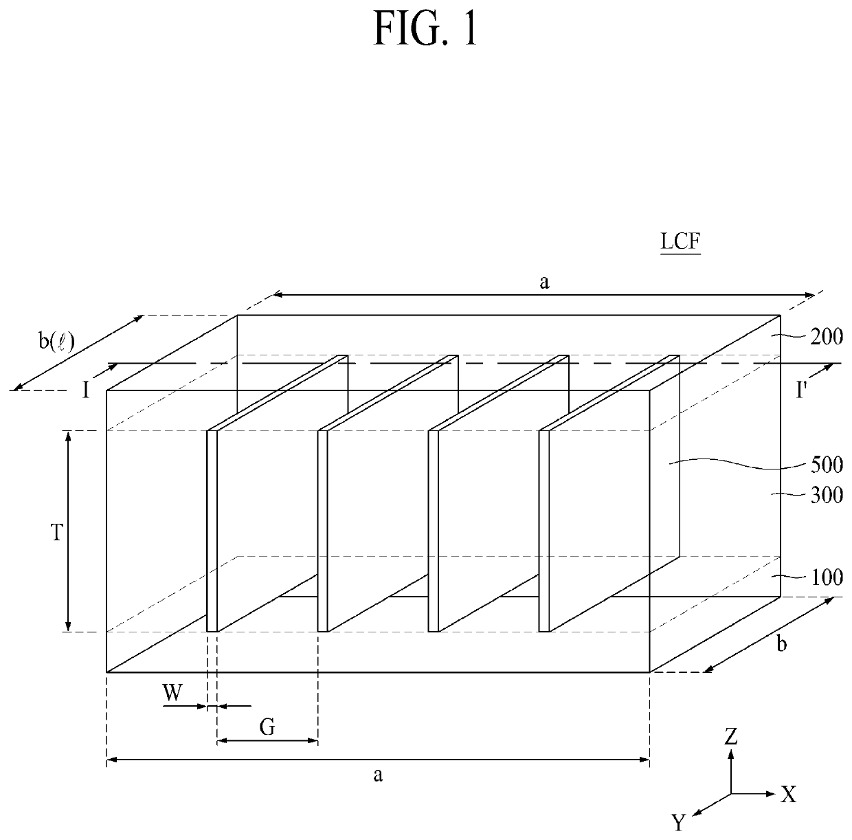
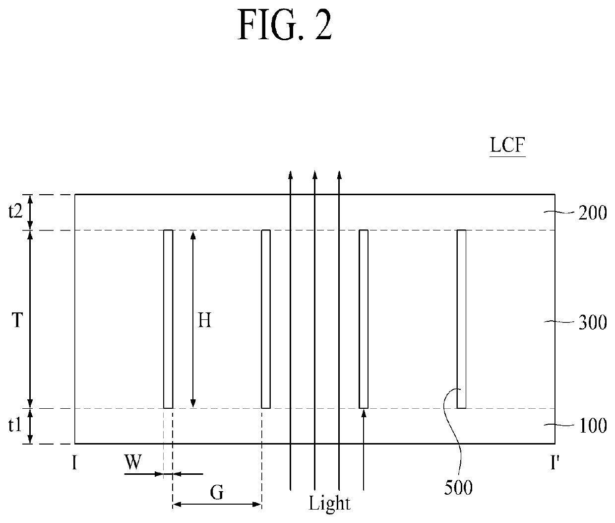
[0056]Hereinafter, referring to figures, we will explain about the light control film having nano light absorbing layers according to the first embodiment of the present disclosure. FIG. 1 is a perspective view illustrating a structure of the light control film having a nano light absorbing layer according to the first embodiment of the present disclosure. FIG. 2 is a cross-sectional view along cutting line I-I′ in FIG. 1, for illustrating a structure of a light control film having a plurality of nano light absorbing layers according to the first embodiment of the present disclosure.

[0057]Referring to FIGS. 1 and 2, the light control film LCF according to the first embodiment of the present disclosure may comprise a lower layer 100, an upper layer 200, a middle layer 300, and a nano light absorbing layer 500. The lower layer 100 may be a thin plate or film having a first thickness t1. The upper layer 200 may be a thin plate or film having a second thickness t2 and the same shape wit...

second embodiment

[0106]Hereinafter, referring to FIG. 5, the second embodiment of the present disclosure will be explained. FIG. 5 is a cross-sectional view illustrating a structure of a light control film and an operating mechanism thereof according to the second embodiment of the present disclosure. The light control film LCF according to FIG. 5 may have a similar structure of the light control film LCF according to FIG. 2. The difference is that the middle layer 300 further includes a prism pattern 300P as contacting on the lower layer 100.

[0107]The prism pattern 300P may include a transparent organic material same as the lower layer 100. In this case, the prism pattern 300P may have the same refractive index as the lower layer 100.

[0108]On the other hand, the middle layer 300 may include the same transparent organic material as the upper layer 200. Otherwise, the middle layer 300 may include different transparent organic material from the prism pattern 300P. In this case, the middle layer 300 an...

third embodiment

[0119]Hereinafter, referring to FIG. 6, we will explain about the third embodiment of the present disclosure. FIG. 6 is a cross sectional view illustrating a structure of the light control film and a mechanism thereof according to the third embodiment of the present disclosure. The light control film LCF shown in FIG. 6 may have the very similar structure of the light control film LCF shown in FIG. 5. The difference in the third embodiment may be that the prism pattern 300P may be upper position of the middle layer 300 as contacting the upper layer 200.

[0120]The prism pattern 300P may have a triangular column shape of which cross-sectional shape is a triangle. For example, the bottom side of the triangle may be in contact with the upper layer 200, the upper vertex may be disposed from the inside of the middle layer 300 toward the lower layer 100. It is preferable that the triangle of the prism pattern 300P may be an isosceles triangle.

[0121]The prism pattern 300P may have the same r...


PUM


Abstract

The present disclosure relates to a light control film having nano (or nano-scale) light absorbing layer and a display using the same. A light control film according to the present disclosure comprises: a lower layer having a first axis and a second axis; an upper layer facing with the lower layer; a middle layer having a thickness disposed between the lower layer and the upper layer; a plurality of nano light absorbing layers arrayed with a predetermined interval along the first axis in the middle layer, each of the nano light absorbing layer having a width along the first axis, a length along the second axis and a height corresponding to the thickness of the middle layer; and a prism pattern disposed between each pair of the nano light absorbing layers.

Description

CROSS-REFERENCE TO RELATED APPLICATIONS[0001]This application claims the benefit of Republic of Korea Patent Application No. 10-2019-0165551 filed on Dec. 12, 2019 which is hereby incorporated by reference in its entirety.BACKGROUNDField[0002]The present disclosure relates to a light control film having nano (or nano-scale) light absorbing layer and a display using the same. Especially, the present disclosure relates to a light control film for narrowly controlling the viewing angle of the display in a specific direction.Discussion of the Related Art[0003]Recently, various types of display such as CRT (cathode ray tube), LCD (liquid crystal display), PDP (plasma display panel) and luminescent display have been developed and prospered. These various types of display are used to display image data of various products such as computers, mobile phones, bank teller machines (ATMs) and vehicle navigation systems in accordance with their unique characteristics.[0004]The display provides th...

Claims


Application Information

Patent Timeline
IPC IPC(8): G02B5/00H01L51/52G02B5/04
CPCG02B5/003G02B5/045H01L51/5284H01L51/5275G02B5/0231H10K59/8792H10K59/879G02B26/08G02B5/22H10K50/858H10K50/865
Inventor SONG, YOUNGKIKIM, SUNMAN
Owner LG DISPLAY CO LTD
Learn More