Temperature control device for chemical liquid used in semiconductor manufacturing process

Pending Publication Date: 2021-07-15
BANG MIN CHEOL
View PDF5 Cites 0 Cited by
  • Summary
  • Abstract
  • Description
  • Claims
  • Application Information

AI Technical Summary

Benefits of technology

The present invention is a temperature control device for chemical liquids that has improved heat transfer efficiency. The device has multiple rows of chemical liquid flow path tubes with the same diameter arranged in rows. The heat transfer from the second heat sink to the chemical liquid is improved by having multiple heating stages and multiple flow paths. The device also has a first and second heat sink block, which allows the chemical liquid to receive heat multiple times while flowing around the first heat sink. The device also includes turbulent flow generating blocks that enhance the heat exchange efficiency. These improvements make it easier and more efficient to control the temperature of the chemical liquid.

Problems solved by technology

According to the conventional double tube type module, bulky devices like a heater, a cooling device, and so on are required to control the temperature of the chemical liquid, and also, it is hard to induce fast changes in the temperature of the chemical liquid.
If impurities are produced by the chemical reactions between the chemical liquid and the components around the chemical liquid, further, various defects may occur in the semiconductor manufacturing process, and in this case, the silicon carbide (SiC) sheets 20 do not have any proved chemical resistance.
If the silicon carbide (SiC) sheets 20 are used, however, defects often occur due to the generation of impurities.
The use of the silicon carbide (SiC) sheets whose chemical resistance is not proved in controlling the temperature of the chemical liquid may cause serious dangers and have many difficulties in manufacturing products.
Further, the chemical liquid jacket 10 is made of perfluoroalkoxy (PFA) whose chemical resistance is proved against high temperature available (allowed for flowing the chemical liquid) and the direct contact with the chemical liquid, but the chemical liquid jacket 10 has low heat transfer efficiency according to the properties of the material.
If the chemical liquid jacket 10 has the shape of a straight tube, especially, a flow of the chemical liquid becomes laminar, thereby making it hard to ensure high heat exchange efficiency.

Method used


Image

  • Temperature control device for chemical liquid used in semiconductor manufacturing process
  • Temperature control device for chemical liquid used in semiconductor manufacturing process
  • Temperature control device for chemical liquid used in semiconductor manufacturing process

Examples


Embodiment Construction

[0035]Hereinafter, the present invention will be in detail described with reference to the attached drawings. However, it is to be understood that the disclosed embodiments are merely exemplary of the invention, which can be embodied in various forms. Therefore, specific structural and functional details disclosed herein are not to be interpreted as limiting, but merely as a basis for the claims and as a representative basis for teaching one of ordinary skill in the art to variously employ the present invention in virtually any appropriately detailed structure. In the drawings, it should be noted that the corresponding parts in the embodiments of the present invention are indicated by corresponding reference numerals.

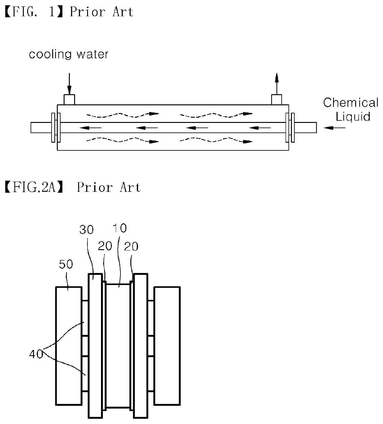
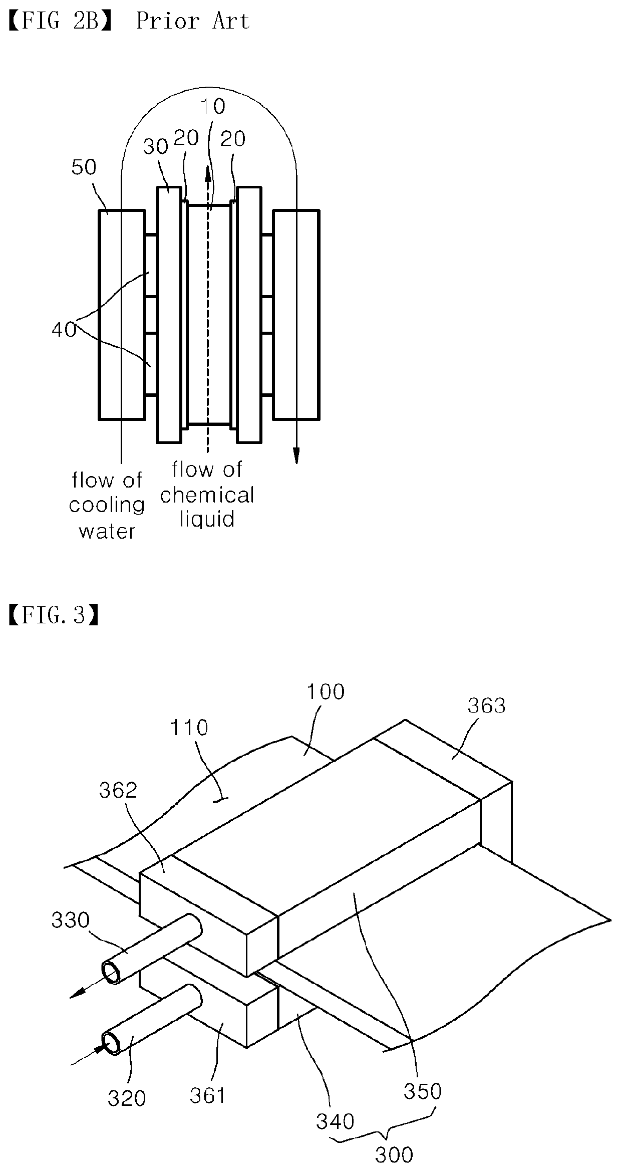
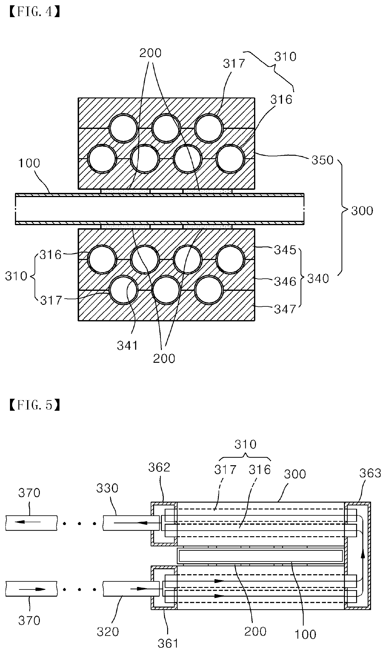
[0036]A temperature control device for a chemical liquid used in a semiconductor manufacturing process according to the present invention is located on a section where the chemical liquid flows in various processes of manufacturing a semiconductor, like wet etching, cle...


PUM


Abstract

A temperature control device for a chemical liquid used in a semiconductor manufacturing process. The device includes: a first heat sink having a cooling water flow path formed therein; a plurality of thermoelectric modules coming into contact with both side surfaces of the first heat sink, respectively; and a second heat sink coming into contact with the thermoelectric modules. The second heat sink includes first and second heat sink blocks, a chemical liquid inlet tube and a chemical liquid outlet tube connected to the first and second heat sink blocks, and a plurality of chemical liquid flow path tubes inserted into the insides of the first and second heat sink blocks in such a manner as to communicate with one another and with the chemical liquid inlet tube and the chemical liquid outlet tube, respectively, to flow the chemical liquid therealong.

Description

CROSS REFERENCE TO RELATED APPLICATION OF THE INVENTION[0001]The present application claims the benefit of Korean Patent Application No. 10-2020-0004302 filed in the Korean Intellectual Property Office on Jan. 13, 2020, the entire contents of which are incorporated herein by reference.TECHNICAL FIELD[0002]The present invention relates to a temperature control device for a chemical liquid used in a semiconductor manufacturing process that has an improvement in a heat transfer structure to thus allow heat generated from a heat generating source to be more efficiently transferred to the chemical liquid.BACKGROUND ART[0003]Generally, a substrate processing apparatus, which performs a semiconductor manufacturing process and a liquid crystal display (LCD) manufacturing process, makes use of various chemical liquids for a substrate manufacturing process.[0004]For example, the substrate processing apparatus performs etching and cleaning for a substrate, and in such substrate manufacturing p...

Claims


Application Information

Patent Timeline
IPC IPC(8): B05C11/10
CPCB05C11/1042H01L21/67017H01L21/67248F28D7/10F28D7/1607F28F13/12H01L21/6704H01L21/67075H10N10/17H10N10/13
Inventor BANG, MIN CHEOL
Owner BANG MIN CHEOL
Why Eureka
Try Eureka