Transaxle

Active Publication Date: 2021-07-15
TOYOTA JIDOSHA KK
View PDF0 Cites 3 Cited by
  • Summary
  • Abstract
  • Description
  • Claims
  • Application Information

AI Technical Summary

Benefits of technology

[0021]With the transaxle according to the aspect of the present disclosure, the radial size of the

Problems solved by technology

In other words, with the configuration of the planetary gear redu

Method used


Image

  • Transaxle
  • Transaxle
  • Transaxle

Examples


Embodiment Construction

[0031]Hereinafter, embodiments of the present disclosure will be described with reference to the drawings. However, in the following embodiments, when numbers of each element, such as the number, the quantity, the amount, the range, etc. thereof, are mentioned, the present disclosure is not limited by the numbers mentioned unless explicitly stated or clearly specified in theory.

1. Configuration of Transaxle According to Present Embodiment

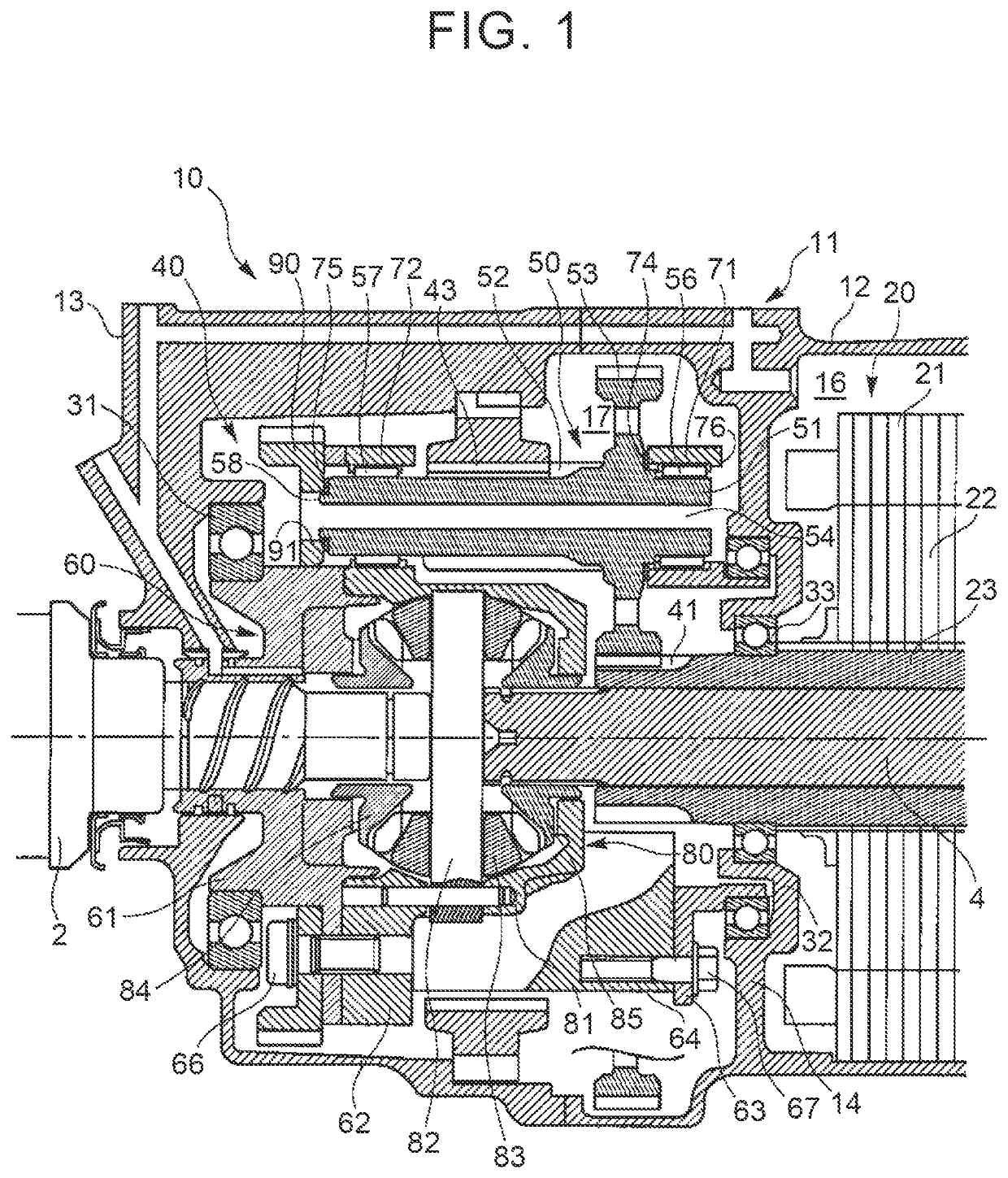
[0032]The configuration of a transaxle according to the present embodiment will be described with reference to FIG. 1. FIG. 1 is a longitudinal sectional view showing a structure of a transaxle 10 according to the present embodiment.

[0033]The transaxle 10 is a device for transmitting a drive force of an electric motor 20 that functions as a drive force unit of a vehicle to a left axle 2 and a right axle 4, and is integrated with the electric motor 20. Specifically, the electric motor 20 is housed in a transaxle case 11 fixed to a vehicle body (not s...


PUM


Abstract

A transaxle includes a planetary gear reducer and a differential device. The planetary gear reducer includes a stepped pinion, a first needle bearing, a second needle bearing, and a carrier. The stepped pinion includes a pinion shaft with which a large diameter pinion and a small diameter pinion are integrated. The first needle bearing is fitted to a part of the pinion shaft outside the large diameter pinion. The second needle bearing is fitted to a part of the pinion shaft outside the small diameter pinion. The carrier is configured to support the stepped pinion via the first needle bearing and the second needle bearing such that the stepped pinion is rotatable with respect to the carrier, and to couple the stepped pinion and the differential device.

Description

CROSS-REFERENCE TO RELATED APPLICATION[0001]This application claims priority to Japanese Patent Application No. 2020-002139 filed on Jan. 9, 2020, incorporated herein by reference in its entirety.BACKGROUND1. Technical Field[0002]The present disclosure relates to transaxles.2. Description of Related Art[0003]In a vehicle that uses an electric motor as a drive force device, a transaxle in which a planetary gear reducer and a differential device are integrated is used as an example of a device that transmits drive force of the electric motor to an axle. The electric motor and the transaxle are also integrated. The electric-motor-integrated transaxle is downsized by disposing the electric motor coaxially with the axle and passing the axle through an output shaft of the electric motor. Further, a stepped pinion composed of a large diameter pinion and a small diameter pinion is adopted as the pinion of the planetary gear reducer. According to the stepped pinion, the diameter of the plane...

Claims


Application Information

Patent Timeline
IPC IPC(8): B60K1/00B60B35/12F16H57/037F16H37/04F16H57/04F16H57/08
CPCB60K1/00B60B35/125F16H57/037F16H37/041F16H2057/02034F16H57/0427F16H57/082B60K2001/001F16H2702/02F16H57/0424B60K17/16F16H1/28F16H37/08F16H48/08F16H57/04F16H57/0471F16H57/0482F16H57/0479F16H57/023F16H57/021F16H57/08B60K17/08F16H2057/02043F16H2057/02086F16H2057/085B60Y2410/10B60Y2410/1022F16H37/082F16H48/06F16H48/38F16H57/0421F16H2048/385F16H2048/423B60K17/12B60T1/005F16H2057/02052
Inventor HIBINO, AKIRASHIINA, TAKAHIRO
Owner TOYOTA JIDOSHA KK
Why Eureka
Try Eureka