
Bearing housing for a flow machine and a flow machine with a bearing housing

a technology of bearing housing and flow machine, which is applied in the direction of bearing unit rigid support, bearing cooling, liquid fuel engine, etc., can solve the problems of high bearing housing cost, limited maximum heat dissipation across the bearing, and increased wear or even bearing failure, so as to reduce the effect of wear and even bearing failure, limiting the maximum heat dissipation, and high bearing housing cos

Pending Publication Date: 2021-07-15
SULZER MANAGEMENT AG
View PDF3 Cites 0 Cited by
  • Summary
  • Abstract
  • Description
  • Claims
  • Application Information

AI Technical Summary

Benefits of technology

This patent aims to improve the bearing housing of a flow machine by adding sufficient cooling to the bearing and lubricant even at high temperatures, which will extend the operation range of the flow machine. The cooling fin is removable and can be adjusted based on the heat load and environmental conditions, making the system more flexible. The cooling fins can be arranged parallel to each other.

Problems solved by technology

It has been found that the conventional methods are very inefficient and limit the maximum heat dissipation across the bearings.
Further, it has been shown in practice, that under certain operating conditions, for example high outside air temperatures, the cooling techniques mentioned are insufficient and expensive, resulting in an increased wear or even bearing failure or high bearing housing costs.

Method used


Image

  • Bearing housing for a flow machine and a flow  machine with a bearing housing
  • Bearing housing for a flow machine and a flow  machine with a bearing housing
  • Bearing housing for a flow machine and a flow  machine with a bearing housing

Examples


first embodiment

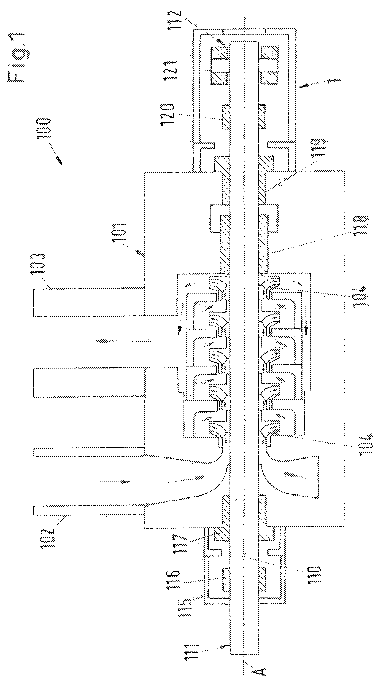
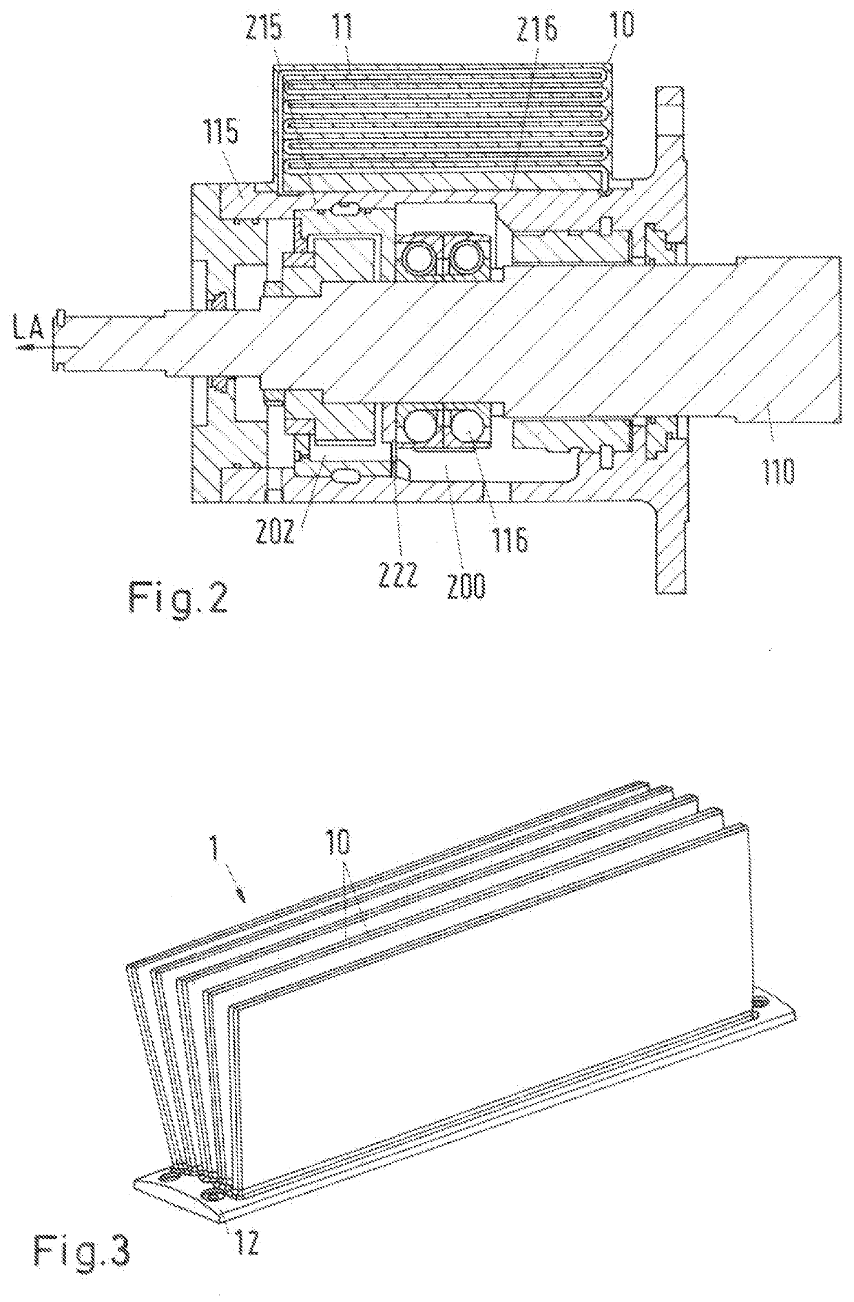
[0040]FIG. 2 shows a sectional view of the bearing housing 115 according to the invention for receiving the drive end 111 of the shaft 110 of the flow machine 100. The bearing housing 115 comprises a bearing axis LA and a bearing chamber 200 for receiving a bearing 116 and a lubricant chamber 202 arranged at the bearing chamber 200 for receiving a lubricant. The bearing chamber 200 is in fluid communication with the lubricant chamber 202 via an opening 222 such that the lubricant can flow between the bearing chamber 200 and the lubricant chamber 202. Furthermore, the bearing housing 115 comprises a wall portion 215 with a cooling fin 10 for dissipating a heat of the lubricant to an environment. For effectively dissipating the heat of the lubricant to the environment the cooling fin 10 comprises a conduit 11 through which the lubricant can be conducted from the lubricant chamber 202 into the bearing chamber 200. The lubricant chamber 202 and the bearing chamber 200 are in fluid commu...

second embodiment

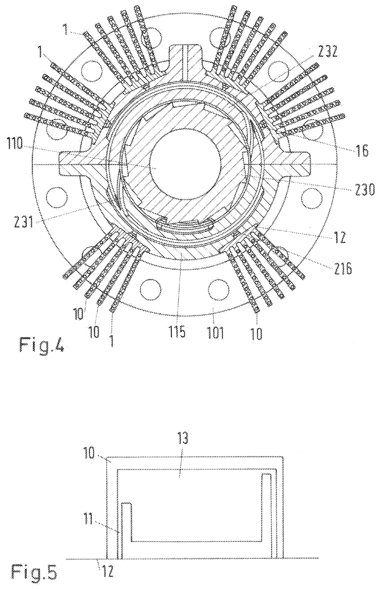
[0047]FIG. 4 shows a sectional view of the bearing housing 115 according an embodiment of to the invention.

[0048]The bearing housing 115 comprises a plurality of fin stacks 1 with a plurality of cooling fins 10. The fin stacks are detachably arranged on the bearing housing 115. The fin stacks 10 are therefore removable and can be constructed via additive manufacturing. The removable fin stacks 1 enable changing of the cooling fins to suit a bearing heat load and environmental conditions. For example, the plurality of cooling fins can be increased (attached) by attaching fin stacks with a higher number of cooling fins, thereby providing a bigger surface for heat exchange. This increases the flexibility of the system.

[0049]A conveying wheel 230 is arranged in the lubricant chamber 202 and is connected to the shaft 110 in a rotationally fixed manner. If the shaft 10 is rotating in the operating state of the pump the conveying wheel 230 is rotating as well. A spiral housing 232 arranged...


PUM


Abstract

A bearing housing for a flow machine includes a bearing chamber configured to receive a bearing, and a lubricant chamber arranged at the bearing chamber and configured to receive a lubricant. The bearing chamber is in fluid communication with the lubricant chamber via an opening such that the lubricant is capable of flowing between the bearing chamber and the lubricant chamber. The bearing housing includes a wall portion with a cooling fin to dissipate heat of the lubricant to an environment. The cooling fin includes a conduit for the lubricant through which conduit the lubricant chamber and the bearing chamber are in fluid communication such that the lubricant is capable of being conducted from the lubricant chamber into the bearing chamber through the conduit to dissipate the heat to the environment.

Description

CROSS-REFERENCE TO RELATED APPLICATION[0001]This application claims priority to European Patent Application No. 20151826.3, filed Jan. 14, 2020, the contents of which are hereby incorporated herein by reference in their entirety.BACKGROUNDField of the Invention[0002]The present disclosure relates to a bearing housing for a flow machine. The present disclosure further relates to a flow machine with a bearing housing.Background Information[0003]Conventional flow machines for conveying a fluid, for example centrifugal pumps, compressors, fans, expanders or turbines typically comprise a stationary machine housing that encloses a rotor, e.g. an impeller, which is arranged on a shaft rotating around an axis of the flow machine. These flow machine generally have at least one bearing unit with a radial and / or axial (thrust) bearing to support the shaft and the rotor. Typically, the bearing unit has a separate bearing housing that is firmly connected to the housing of the flow machine. In th...

Claims


Application Information

Patent Timeline
IPC IPC(8): F04D29/063F04D29/58F04D29/056F04D29/053F04D29/42
CPCF04D29/063F04D29/582F04D29/4206F04D29/053F04D29/056F04D29/0462F04D29/061F04D29/586F16C37/007F04D29/588F16C2360/44F16C35/042
Inventor GRANT, SEAN
Owner SULZER MANAGEMENT AG
Learn More