
Strength training equipment

a training equipment and strength technology, applied in the field of strength training equipment, can solve the problems of affecting the exercise function of the exerciser, affecting the exerciser's comfort, and requiring a lot of time and effort for the user to adjust, so as to and reduce the occupying of space

Active Publication Date: 2021-07-22
CHI HUA FITNESS
View PDF0 Cites 6 Cited by
  • Summary
  • Abstract
  • Description
  • Claims
  • Application Information

AI Technical Summary

Benefits of technology

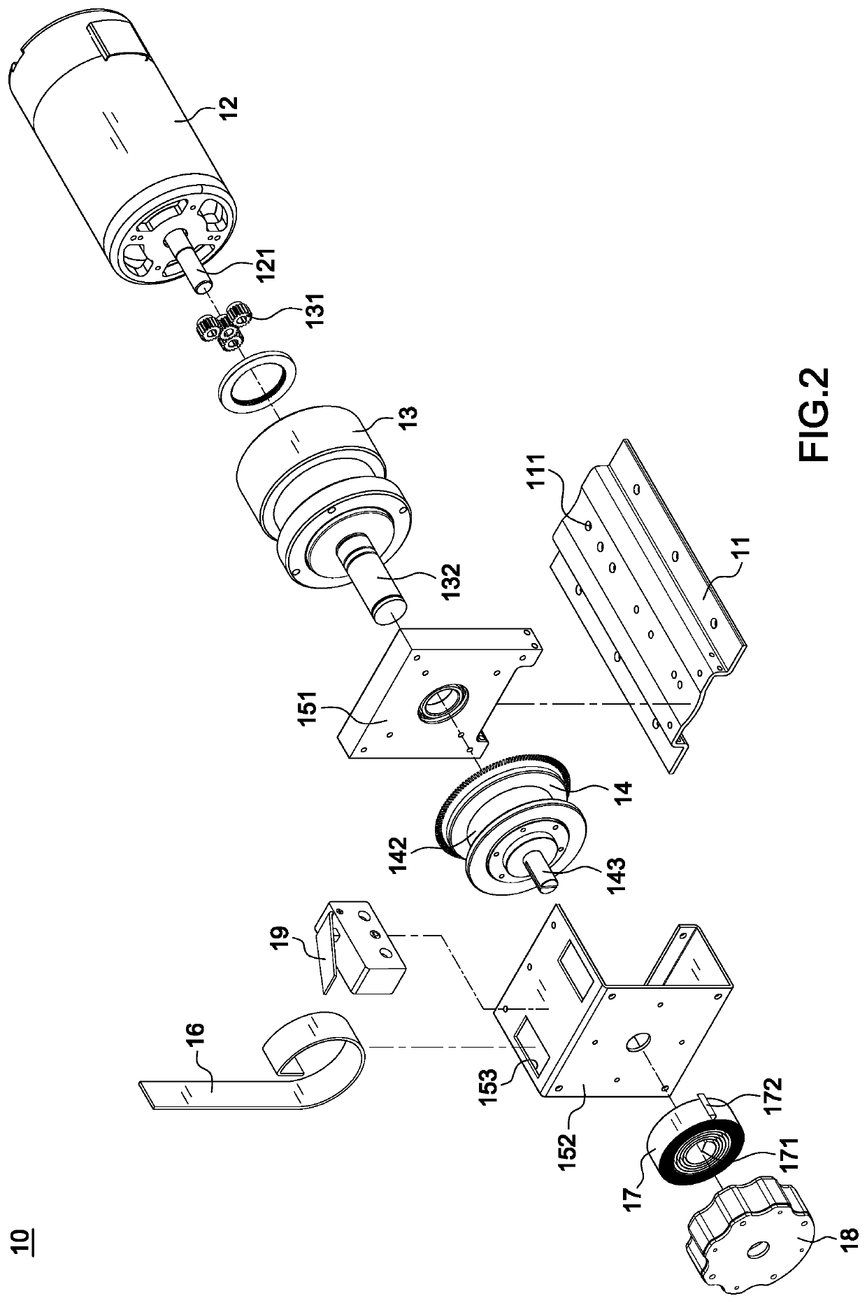
The present invention provides a strength training equipment that uses a motor to produce torque, replacing the traditional iron weight plates. The motor, deceleration machine, and winding wheel are connected in the same shaft, reducing transmission loss and creating an integrated structure that takes up less space. Additionally, the strength training equipment includes a spiral spring that produces torque in the opposite direction to the main shaft, without spinning the shaft when rewound. Finally, sensors are connected to the controller and use a servo control unit to smoothly control the load and compensate for load current, creating a more realistic setting for users.

Problems solved by technology

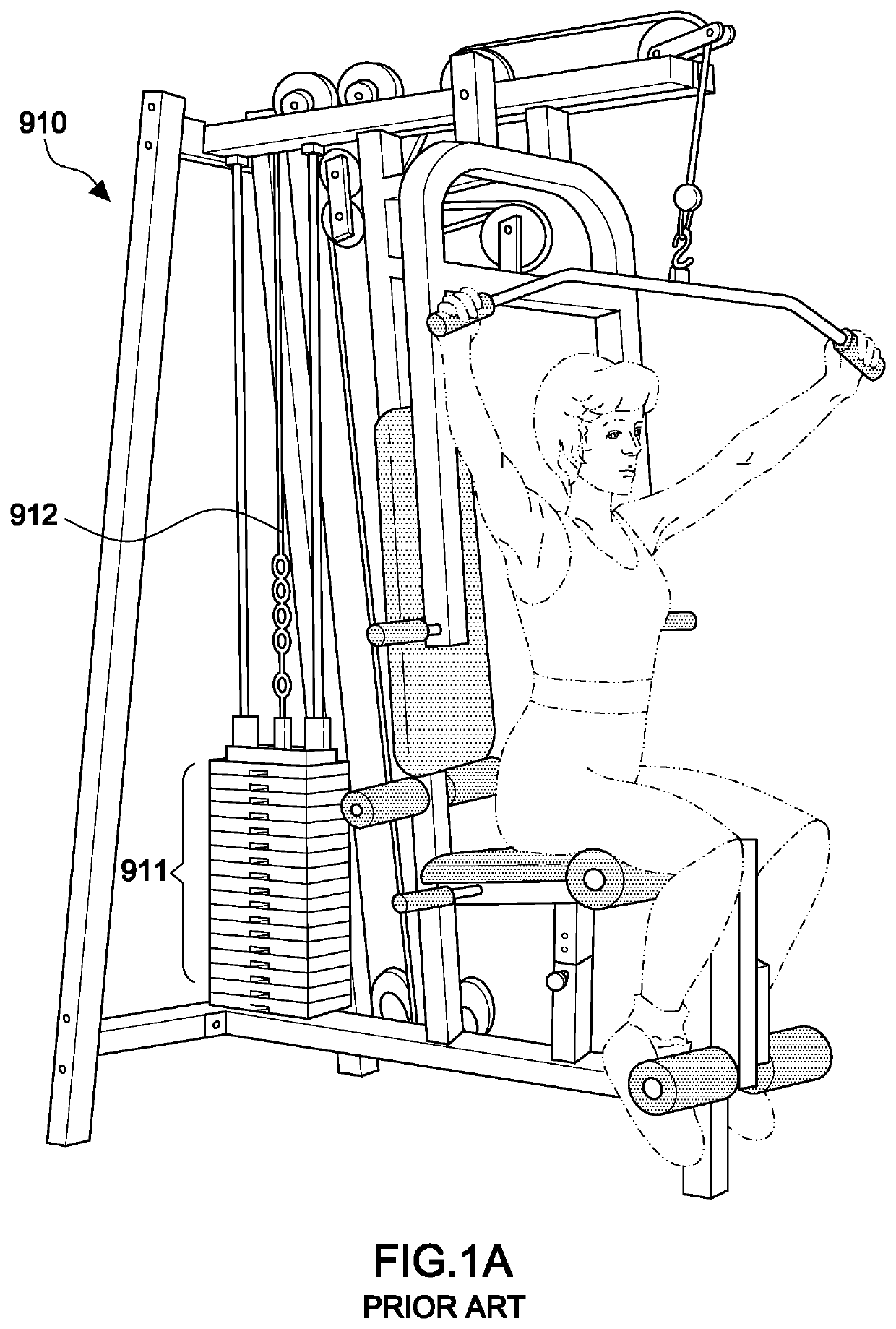
Such conventional strength trainer has the following shortcomings:1. The iron weight plate 911 comes with a large volume and occupies much space, it will take much time and effort for the user to make the adjustment.2. If the load such as the iron weight plate 911 is lifted by a transmission cable 912 and then released slowly, an annoying sound will be produced, and the irritating sound will cause discomfort to the exerciser.3. The load cannot be changed by setting an exercise curve, as a result, the exercising function is limited.
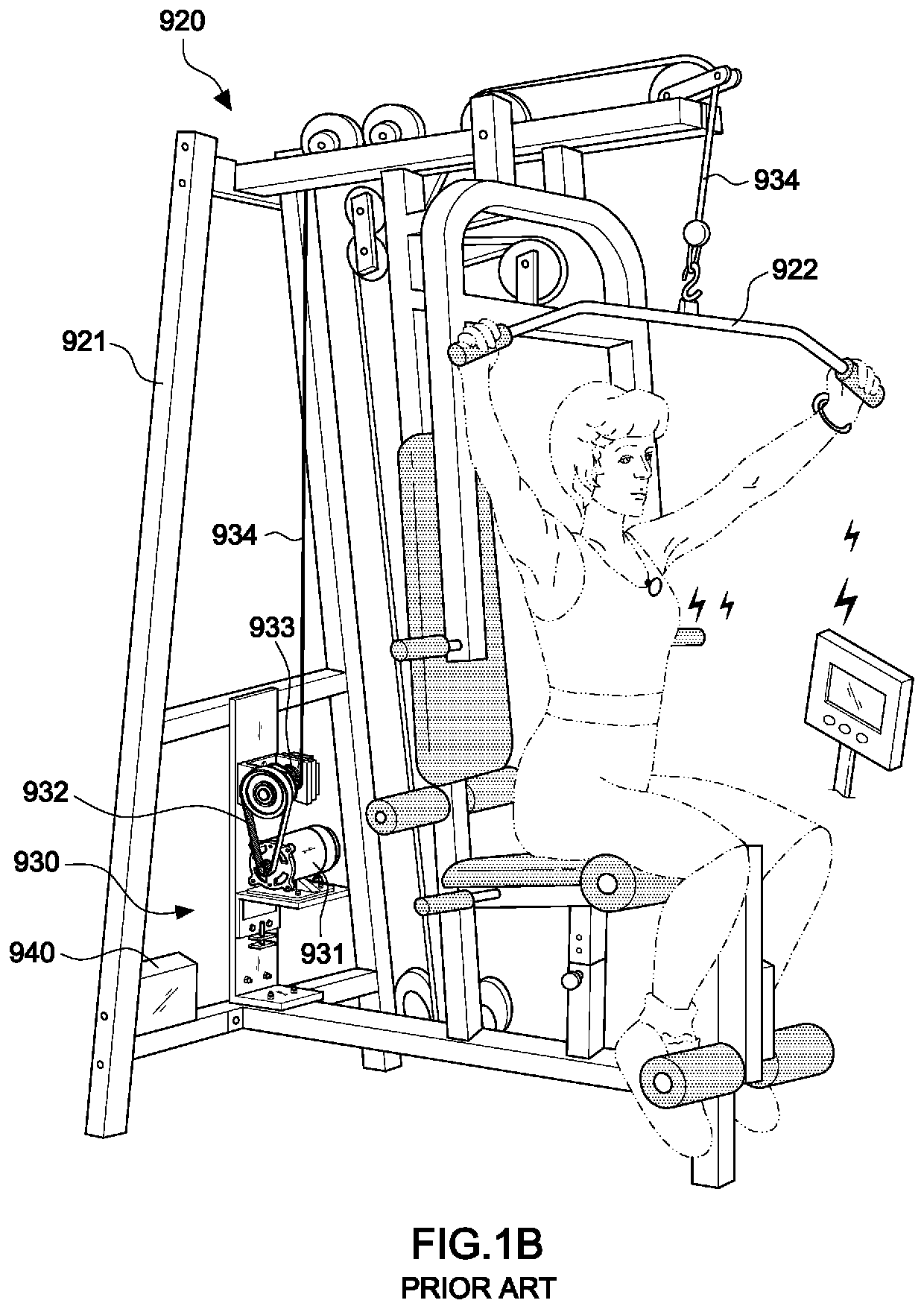
However, reviewing the mechanism shown in FIG. 1B, the aforementioned prior arts still have the following drawbacks:1. During the process of force applying, the transmission element 932 slide, and affect the training effect.2. The motor 931 and the winch 933 are not in the same shaft, taking up a large space.3. The structure is only suitable for extension strength training, lack of the mechanism for swinging strength training, the exercising function is limited.

Method used


Image

  • Strength training equipment
  • Strength training equipment
  • Strength training equipment

Examples


Embodiment Construction

[0034]Referring to FIGS. 2-5, a torque producing mechanism 10 of the present invention, comprising: a motor 12, a deceleration machine 13, and a winding wheel 14, each of them is fixed on the positioning hole 111 of a base plate 11 and connected to each other on the same shaft; wherein the motor 12 is a direct current (DC) motor or a brushless motor which shaft center 121 connected to a speed change gear train 131 of the deceleration machine 13, the deceleration machine 13 having a protruding output shaft 132 with an one-way bearing 133 set in a shaft hole 141 of the winding wheel 14; a belt 16 winding the wheel hub 142 of the winding wheel 14 and connecting to a steel wire 23 at the free end 161, while the steel wire 23 is pulled by the applied force, the motor 12 outputs torque in the opposite direction of the applied force to the steel wire 23; a bracket 151 arranged on the base plate 11 and beside the deceleration machine 13, a fixing bracket 152 with U shape arranged at the lat...


PUM


Abstract

A strength training equipment, comprising: a torque producing mechanism, a weight pulling mechanism, a controller, and an electronic instrument; wherein the torque producing mechanism is composed of the deceleration machine and the winding wheel connected to each other on the same shaft, a belt is winding on the winding wheel, and the free end of the belt is connected to the force applied unit of the weight pulling mechanism; a movement path sensor installed on the winding wheel, and an angle sensor installed at the lateral side of the guide pulley of the weight pulling mechanism; whereby inputting required torque value by electronic instrument, the servo control unit will drive the motor to produce torque, the user will have to against the torque while applying force to the extension element and the swinging element, so achieve the effect of strength training.

Description

BACKGROUND OF THE INVENTION1. Field of the Invention[0001]The invention relates to a strength training equipment, especially to one that has a motor providing linear moment to replace a traditional iron weight plate as a load element and has a servo control unit performing a curved load control and appropriately compensating a load current.2. Description of the Related Art[0002]Regardless of recreation, health or professional reasons, fitness exercise is an important part of our life. For example, strength trainers become very popular in developed countries in Europe and America, and iron weight plates are used to build up muscles, promote physiological functions, and maintaining good health. Thus, the iron weight plate is called a “weight strength trainer”, whose structure is shown in FIG. 1A. Such conventional strength trainer has the following shortcomings:[0003]1. The iron weight plate 911 comes with a large volume and occupies much space, it will take much time and effort for t...

Claims


Application Information

Patent Timeline
Patent Type & Authority Applications(United States)
IPC IPC(8): A63B24/00A63B21/005A63B21/00
CPCA63B24/0087A63B21/0058A63B21/153A63B2220/833A63B2220/16A63B2024/0093A63B2220/805A63B21/154A63B22/0002A63B2225/50
Inventor LEE, CHIA-JUNG
Owner CHI HUA FITNESS
Learn More