Electric working machine and method for assembling the same

Active Publication Date: 2021-07-29
YAMABIKO CORP
View PDF0 Cites 1 Cited by
  • Summary
  • Abstract
  • Description
  • Claims
  • Application Information

AI Technical Summary

Benefits of technology

The present invention provides an electric working machine and a method for assembling it without the need for specific jigs, which makes the assembly process easier and reduces production costs. The motor and rod fixture are integrally formed as a single article, eliminating the need for separate components. The motor assembly can be easily secured to the body casing and aligned automatically, thereby simplifying the assembly process and eliminating the need for specific jigs. The motor assembly can also be attached to the body casing only by screwing bolts from the outer side of the body casing, further facilitating the assembly process.

Problems solved by technology

This has caused a problem of requiring enormous labor and time for the assembling work.

Method used


Image

  • Electric working machine and method for assembling the same
  • Electric working machine and method for assembling the same
  • Electric working machine and method for assembling the same

Examples


Embodiment Construction

[0035]An exemplary embodiment of the present disclosure will be described below with reference to the drawings.

[Configuration of Electric Working Machine]

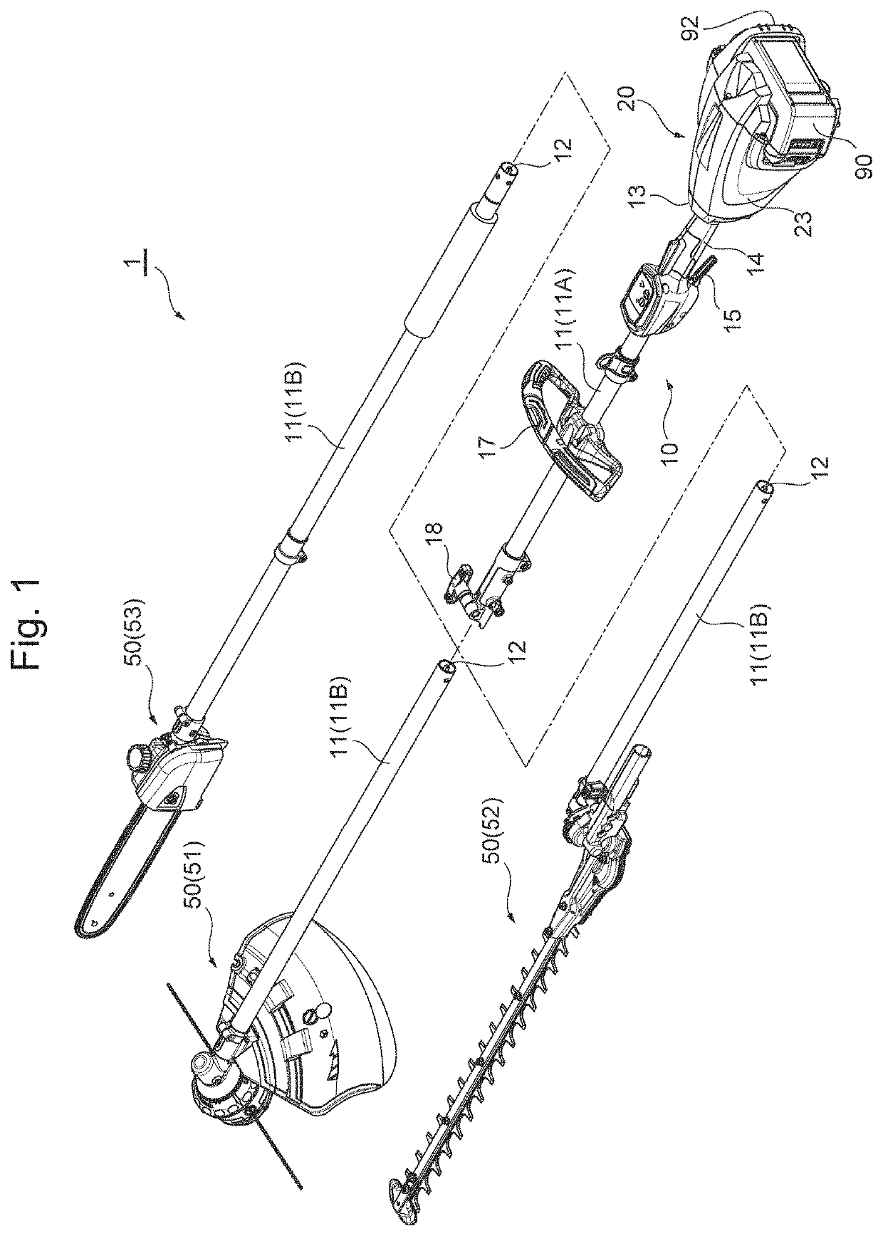
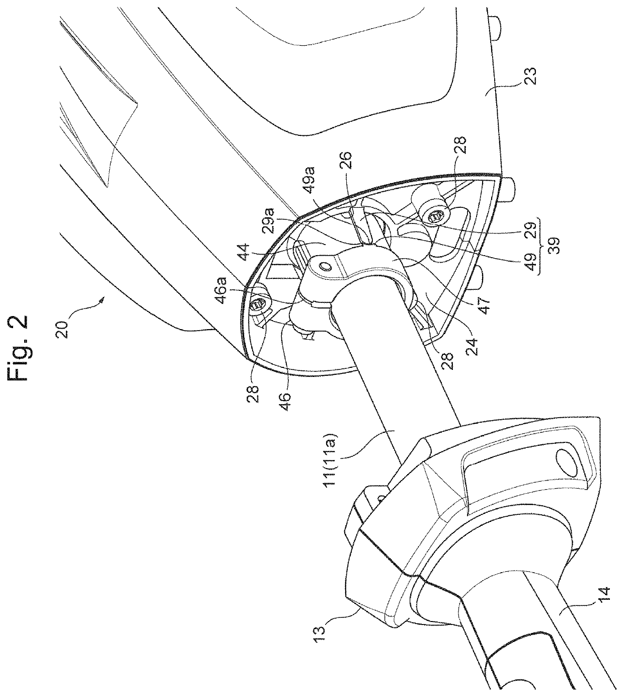
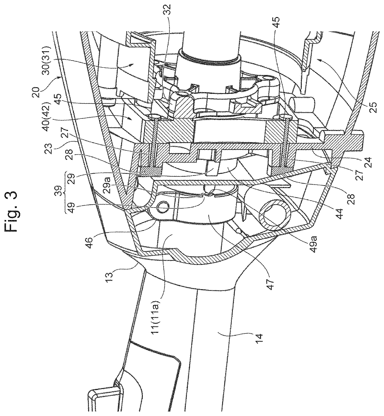
[0036]FIG. 1 is a perspective view of a common machine body 10 and three types of exchangeable working parts (also referred to as attachments) 50 (51, 52, and 53) of an electric working machine 1 of an embodiment according to the present disclosure. FIG. 2 is a perspective view showing the inside of the electric working machine 1 illustrated in FIG. 1 with a cap 13 removed from the front end of a body casing 23. FIG. 3 is a perspective view showing the inside of the electric working machine 1 illustrated 1 in FIG. 1 as viewed from a cut-out portion near a proximal end 11a of an operating rod 11 and a cut-out front portion of the body casing 23. FIG. 4 is a longitudinal cross-sectional view of the proximal end 11a of the operating rod 11 and the front half portion of a body 20 of the electric working machine 1 illustrated in FIG. 1....


PUM


Abstract

An electric working machine and method for assembling the same that do not require specific jigs, so as to facilitate assembling work and reduce man-hours and production cost. A motor assembly is relatively inserted into a body casing, with a mounting base disposed behind a partitioning wall portion allowing a tubular fixture to project through an insertion hole toward the front of the partitioning wall portion, and a temporarily securing mechanism temporarily secures the motor assembly to retain the position of the motor assembly by automatically moving it in rotating and two orthogonal directions on a plane along the partitioning wall portion, so as to coaxially arrange the tubular fixture and insertion hole, and through-hole and screw hole of the mounting base for screwing the bolt. In such a temporarily secured state, the motor assembly is finally secured by screwing the bolt through the through-hole into the screw hole of the mounting base.

Description

RELATED APPLICATIONS[0001]This application claims priority to Japanese Patent Application No. 2020-010321, filed on Jan. 24, 2020, the entire content of which is incorporated herein by reference.BACKGROUND OF THE INVENTION1. Field of the Invention[0002]The present disclosure relates to an electric working machine driven by an electric motor to be operated, such as a bush cutter, hedge trimmer, and chain saw, and a method for assembling such an electric working machine.2. Description of the Related Art[0003]As disclosed in JP 2014-239704 A, JP 2010-200673 A, or JP 2014-147398 A, portable electric working machines driven by an electric motor (hereinafter simply referred to as a motor) to be operated typically include a motor as the driving source for operation, a synthetic resin body casing in which the motor is disposed, an operating rod with its distal end side provided with a working part and its proximal end side securely attached to the body casing, and a rod fixture (also referr...

Claims


Application Information

Patent Timeline
IPC IPC(8): H02K7/14B25F5/00H02K5/20H02K9/06H02K15/14A01G3/08A01G3/053A01D34/416
CPCH02K7/145B25F5/008H02K5/207H02K9/06B25F3/00A01G3/086A01G3/053A01D34/416H02K15/14H02K7/14H02K5/20H02K5/04H02K11/0094H02K15/00A01D69/02A01D34/90B25F5/00A01G2003/0461
Inventor MOMIYAMA, HIROSHI
Owner YAMABIKO CORP
Why Eureka
Try Eureka