


Quick Research
Generate reliable direction feasibility study reports for your R&D in just a few steps.

Technical Q&A
Discover and master advanced knowledge NOW. Basics, ideas, possibilities, all at once.

Find Solutions
As an expert in R&D theories, this can generate solutions to your technical problems instantly.

Evaluate Feasibility
Analyze your overall solution with one click, know your potential R&D risks in advance.

Monitor Landscape
Get weekly tech updates, stay abreast of the latest tech innovations and key insights.
Method and apparatus for additive manufacturing of a component
- Summary
- Abstract
- Description
- Claims
- Application Information
AI Technical Summary
Benefits of technology
Problems solved by technology
Method used
Image

Examples
embodiment 1
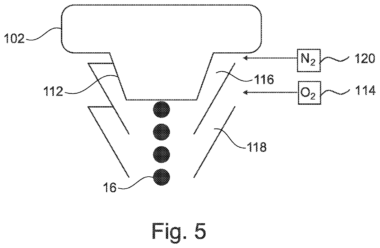
[0068]2. Method according to the above Embodiment 1, wherein the at least one operating parameter includes an amount of a cooling medium, for example, a protective gas such as N2 or air, which is supplied, wherein the change is effected such that the temperature of the material (16) that is applied during formation of the separation structure (14), and / or of the material (16) to which the separation structure (14) is applied is reduced relative to the temperature of the material (16) when the component (10) is formed.
[0069]3. Method according to the above Embodiment 1 or 2, wherein the at least one operating parameter includes an oxygen concentration, wherein the change is effected such that a degree of oxidation of the material (16) that is applied when forming the separation structure (14) and / or of the material (16), to which the separation structure (14) is applied, is increased relative to a degree of oxidation of the material (16) when the component (10) is formed.
embodiment 3
[0070]4. Method according to the above Embodiment 3, further comprising:
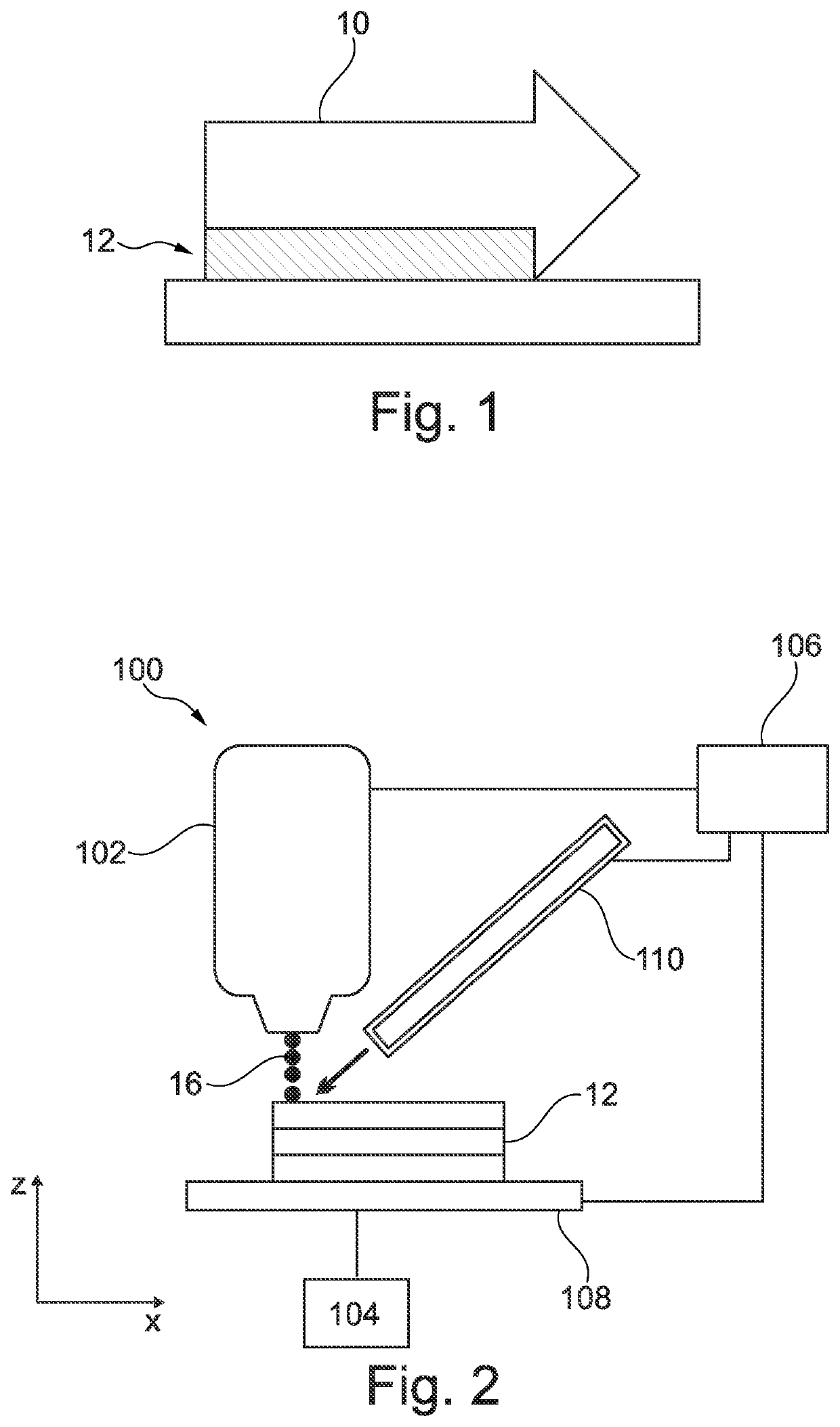
[0071]supplying a protective gas in a region of an opening (112) of the printhead (102); and
[0072]supplying an oxidizing gas in a region downstream of the supply of the protective gas to increase the degree of oxidation of the applied material (16) during the formation of the separation structure (14).
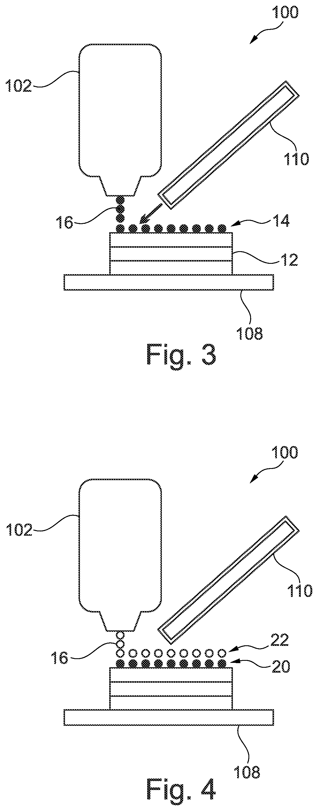
[0073]5. Method according to any one of the above Embodiments 1 to 4, wherein the applying of the liquid material (16) is effected layer by layer, wherein a layer (20) of the separation structure (14) has substantially a same height as a layer (22) of the component (10).
embodiment 5
[0074]6. Method according to the above Embodiment 5, wherein the separation structure (14) has one to five layers (20), in particular is formed from a single layer (22).
[0075]7. Method according to the above Embodiment 5 or 6, further with changing of at least one additional operating parameter during the formation of the separation structure (14) to adjust the height of the layer (20), wherein the at least one additional operating parameter includes, for example, a size, a speed and / or a time interval of droplets of the applied material (16).
[0076]8. Method according to any one of the preceding Embodiments, wherein the at least one operating parameter is changed such that the distances between the droplets of the material of the separation structure (14) are increased, so that porous structures having reduced strength are produced.
PUM
| Property | Measurement | Unit |
|---|---|---|
| Temperature | aaaaa | aaaaa |
| Time | aaaaa | aaaaa |
| Concentration | aaaaa | aaaaa |
Abstract
Description
Claims
Application Information
 - R&D Engineer
- R&D Manager
- IP Professional
- Industry Leading Data Capabilities
- Powerful AI technology
- Patent DNA Extraction
Browse by: Latest US Patents, China's latest patents, Technical Efficacy Thesaurus, Application Domain, Technology Topic, Popular Technical Reports.
© 2024 PatSnap. All rights reserved.Legal|Privacy policy|Modern Slavery Act Transparency Statement|Sitemap|About US| Contact US: help@patsnap.com