
Scene crop via adaptive view-depth discontinuity

Active Publication Date: 2021-08-26
AUTODESK INC
View PDF0 Cites 0 Cited by
  • Summary
  • Abstract
  • Description
  • Claims
  • Application Information

AI Technical Summary

Benefits of technology

The invention uses the depth map of each view of an image or camera to determine which parts of the image are a low confidence point. By combining all the views, the invention is able to accurately keep high confidence subject elements intact while removing distant objects. The technical effect of the invention is to improve the accuracy and reliability of image analysis and processing.

Problems solved by technology

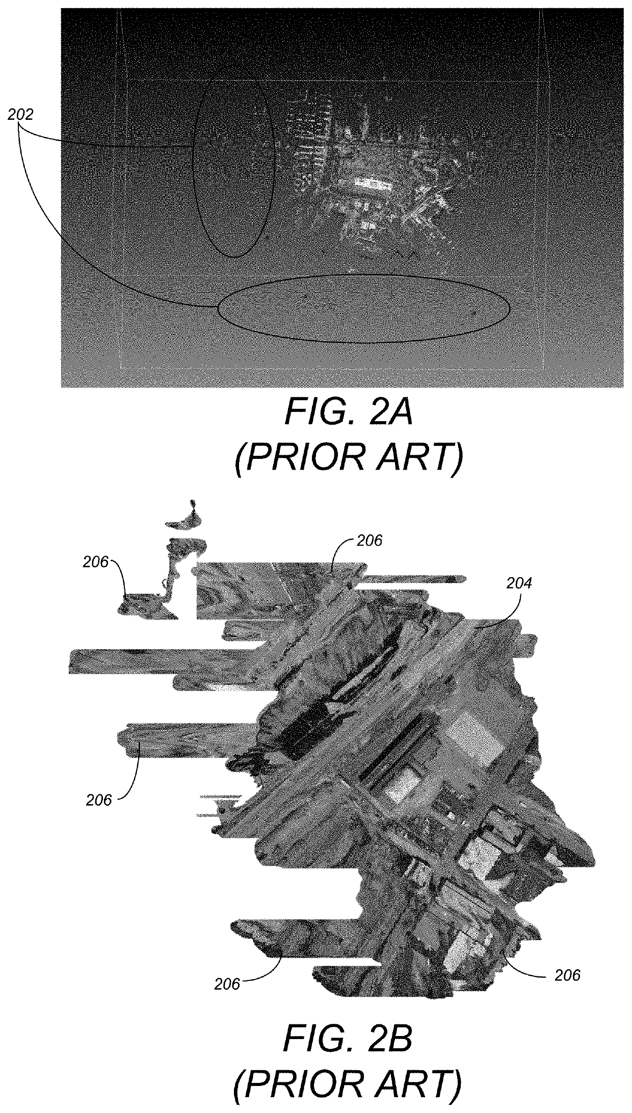
However, while such a camera position-based cropping may work for Nadir shots, it is unable to correctly handle oblique or façade shots.
Specifically, because such a mechanism only relies on creating a convex hull from the XY projection of the camera position, it is unable to account for view-depth information resulting in over-cropping (only points near the camera are kept but not those the camera is actually looking at).

Method used


Image

  • Scene crop via adaptive view-depth discontinuity
  • Scene crop via adaptive view-depth discontinuity
  • Scene crop via adaptive view-depth discontinuity

Examples


Embodiment Construction

[0022]In the following description, reference is made to the accompanying drawings which form a part hereof, and which is shown, by way of illustration, several embodiments of the present invention. It is understood that other embodiments may be utilized and structural changes may be made without departing from the scope of the present invention.

Logical Flow

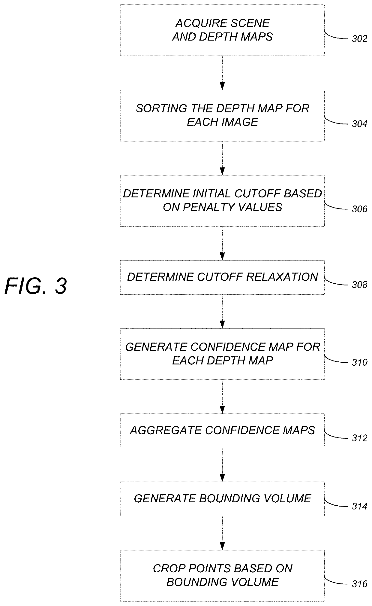
[0023]FIG. 3 illustrates the logical flow for cropping a three-dimensional (3D) scene in accordance with one or more embodiments of the invention.

[0024]At step 302, the 3D scene is acquired. The 3D scene consists of multiple 3D images, with each 3D image captured from a view angle of an image capture device. Such an image capture device may be a camera capturing an image or may be a laser scanner capturing a point cloud. The 3D scene also includes a depth map for each 3D image. The depth map includes two or more depth values, with each of the two or more depth values measured from the image capture device to an object in the 3D i...


PUM


Abstract

A method, apparatus, and system provide the ability to crop a three-dimensional (3D) scene. The 3D scene is acquired and includes multiple 3D images (with each image from a view angle of an image capture device) and a depth map for each image. The depth values in each depth map are sorted. Multiple initial cutoff depths are determined for the scene based on the view angles of the images (in the scene). A cutoff relaxation depth is determined based on a jump between depth values. A confidence map is generated for each depth map and indicates whether each depth value is above or below the cutoff relaxation depth. The confidence maps are aggregated into an aggregated model. A bounding volume is generated out of the aggregated model. Points are cropped from the scene based on the bounding volume.

Description

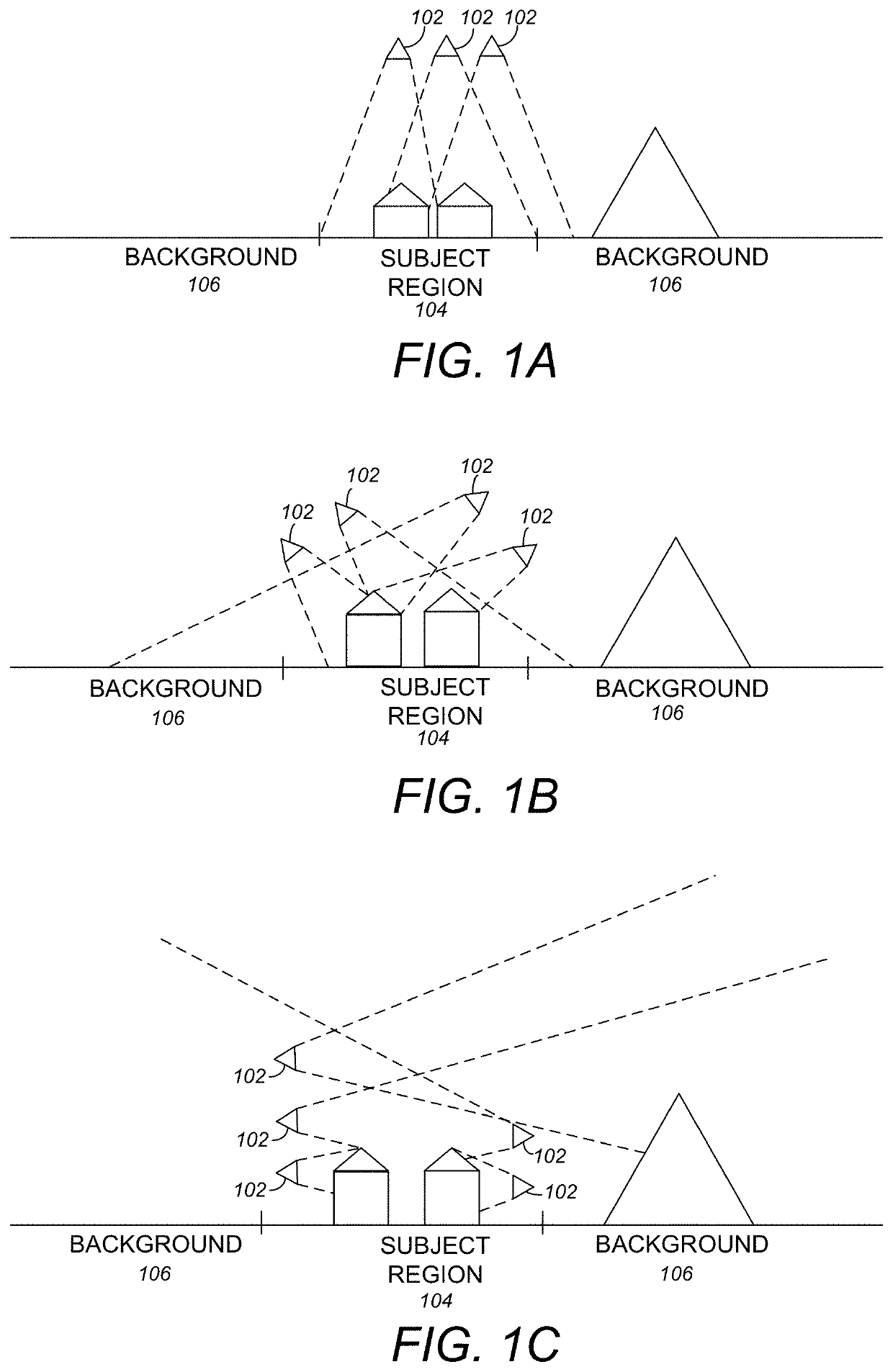
BACKGROUND OF THE INVENTION1. Field of the Invention[0001]The present invention relates generally to image processing, and in particular, to a method, system, apparatus, and article of manufacture for an adaptively cropping depth-based images.2. Description of the Related Art[0002]Images often contain distant or non-subject objects. The problem becomes how to effectively and efficiently crop such objects out of the images To better understand this problem, a description of image reconstruction and cropping may be useful.[0003]Three-dimensional scenes may often be constructed / reconstructed using various photogrammetry / point cloud processing techniques In particular, multiple cameras / point cloud scanners (e.g., laser scanners) may capture images of a scene that are then combined to create the 3D scene. Each captured image has associated depth data identifying the depth from the camera / scanner origin to the object in the scene There are often three different views that are captured: (1...

Claims


Application Information

Patent Timeline
IPC IPC(8): G06T15/30G06T7/593H04N13/271
CPCG06T15/30G06T7/593G06T2207/10028G06T2210/22H04N13/271G06T19/00G06T2210/12G01C11/06H04N13/128G01S17/89
Inventor NAIMIN, KOHJIANG, LI
Owner AUTODESK INC
Learn More