Stereolithography apparatus equipped for detecting amount of resin, and method of operating same

Pending Publication Date: 2021-09-02
PLANMECA
View PDF0 Cites 1 Cited by
  • Summary
  • Abstract
  • Description
  • Claims
  • Application Information

AI Technical Summary

Benefits of technology

The invention is a stereolithography apparatus and method that makes it simple and reliable to detect the surface level of resin in the vat. This is achieved by using an optical radiator to project a pattern onto the vat and an optical imaging detector to capture the pattern reflected on the surface. The optical image data is then used to calculate the amount of resin in the vat. The technical effects of this invention include improved accuracy and reliability in detecting the resin level, as well as simplified and cost-effective operation of the stereolithography apparatus.

Problems solved by technology

In general, making the operation of a stereolithography apparatus easy and straightforward for even inexperienced users involves several challenges.
The user may consider it tedious and inconvenient to carry the responsibility of programming the apparatus with the correct parameter values every time.
The resins are relatively expensive, for which reason care should be taken to not allow too much resin to enter the vat and to utilize as much of the remaining resin as possible for actual manufacturing jobs.

Method used


Image

  • Stereolithography apparatus equipped for detecting amount of resin, and method of operating same
  • Stereolithography apparatus equipped for detecting amount of resin, and method of operating same
  • Stereolithography apparatus equipped for detecting amount of resin, and method of operating same

Examples


Embodiment Construction

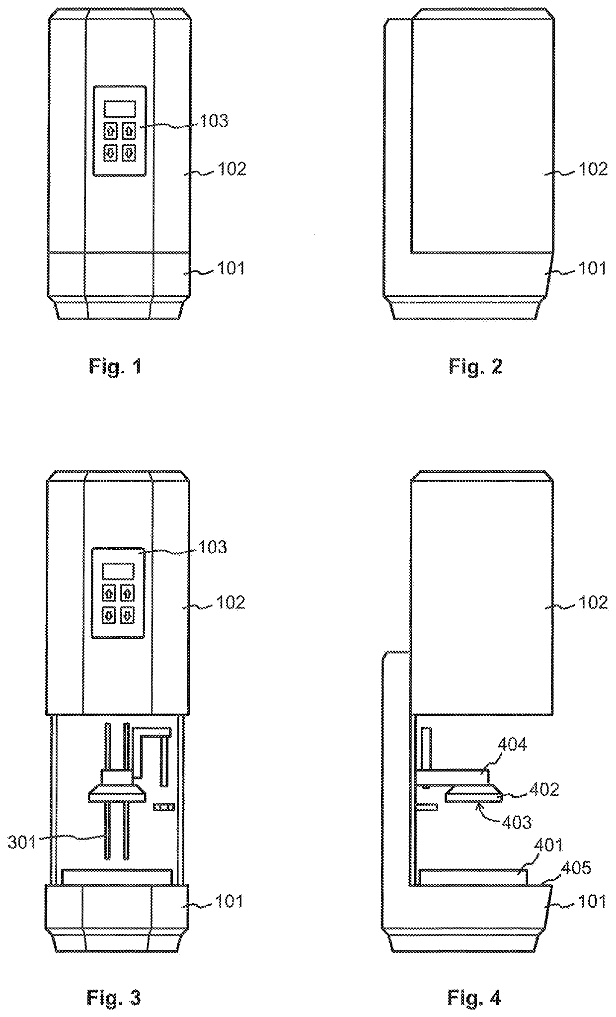
[0048]FIGS. 1 to 4 illustrate an example of a stereolithography apparatus. The apparatus could also be called a stereolithographic 3D printer, or a stereolithographic additive manufacturing apparatus. Basic parts of the apparatus are a base part 101 and a lid 102, of which the lid 102 is movably coupled to the base part 101 so that it can move between a closed position shown in FIGS. 1 and 2 and an open position shown in FIGS. 3 and 4. Here the direction of the movement is vertical, but this is not a requirement; the movement of the lid 102 in relation to the base part 101 could take place in other directions. An important advantage of a movable lid of this kind is that an ongoing stereolithographic 3D printing process can be protected from any interfering external optical radiation by closing the lid 102.

[0049]A vat 401 is provided in the base part 101 for holding resin for use in the stereolithographic 3D printing process. If the vat 401 is not a fixed part of the stereolithograph...


PUM

PropertyMeasurementUnit
Lengthaaaaaaaaaa
Dimensionaaaaaaaaaa
Wavelengthaaaaaaaaaa

Abstract

A stereolithography apparatus comprises a fixed vat (401) or a holder for receiving a removable vat for holding resin for use in a stereolithographic 3D printing process, an optical radiator (901) configured to project a pattern upon a portion of said vat (401), an optical imaging detector *501 (field of view, installed and directed so that said portion of said vat (401) and / or a surface onto which the projected pattern is reflected—is within said field of view when said optical imaging detector (501) is in an operating position, and a controller (502, 2001) coupled to said optical imaging detector (501) for receiving optical image data from said optical imaging detector (501). Said controller (502, 2001) is configured to use said optical image data to calculate an amount of resin in said vat (401).

Description

FIELD OF THE INVENTION[0001]The invention concerns the technology of stereolithographic 3D printing, also known as stereolithographic additive manufacturing. In particular the invention concerns the utilization of obtained image data in optimizing the use of resin in a stereolithography apparatus.BACKGROUND OF THE INVENTION[0002]Stereolithography is a 3D printing or additive manufacturing technique in which optical radiation is used to photopolymerize suitable raw material to produce the desired object. The raw material comes to the process in the form of a resin. A vat is used to hold an amount of resin, and a build platform is moved in the vertical direction so that the object to be produced grows layer by layer, beginning on a build surface of the build platform. The optical radiation used for photopolymerizing may come from above the vat, in which case the build platform moves downwards through the remaining resin as the manufacturing proceeds. The present description concerns i...

Claims


Application Information

Patent Timeline
IPC IPC(8): B29C64/393G06T7/521G06T7/73B33Y10/00B33Y30/00B33Y50/02B29C64/135B29C64/268B29C64/255B33Y40/00
CPCB29C64/393G06T7/521G06T7/73B33Y10/00B29C64/255B33Y50/02B29C64/135B29C64/268B33Y30/00B33Y50/00B29C64/124B29C64/20B29C64/386B33Y40/00G01B11/25G01B11/28B29C64/277
Inventor MYLLYLA, TUOMASRAKKOLAINEN, TEROVUORIO, VILLEKOPONEN, JARITOIMELA, LASSE
Owner PLANMECA
Why Eureka
Try Eureka