
Apparatus for polishing, processing system, and method of polishing

a technology for polishing apparatus and processing system, which is applied in the direction of grinding carriages, manufacturing tools, lapping machines, etc., can solve the problems and not taking into account the maintenance rate of the substrate. , to achieve the effect of reducing the use amount of polishing solution and maintaining the polishing rate of the substra

Pending Publication Date: 2021-09-16
EBARA CORP
View PDF9 Cites 1 Cited by
  • Summary
  • Abstract
  • Description
  • Claims
  • Application Information

AI Technical Summary

Benefits of technology

The patent text is discussing a way to reduce the cost of polishing solutions used in semiconductor device manufacturing. The problem is that expensive polishing solutions are used in large amounts and have to be treated after use. To solve this problem, the text proposes a method to reduce the amount of polishing solution used while maintaining a good polishing rate of the substrate. The solution is to supply the polishing solution efficiently between the polishing pad and the substrate. The goal is to save money and reduce waste while maintaining polishing efficiency.

Problems solved by technology

This apparatus, however, does not take into account maintaining the polishing rate of a substrate and reducing the use amount of a polishing solution.
More specifically, the polishing solution used for the polishing apparatus is expensive, and an additional cost is required to treat the used polishing solution.
Simply reducing the supply amount of the polishing solution undesirably lowers the polishing rate of the substrate.

Method used


Image

  • Apparatus for polishing, processing system, and method of polishing
  • Apparatus for polishing, processing system, and method of polishing
  • Apparatus for polishing, processing system, and method of polishing

Examples


first embodiment

(General Configuration of Polishing Apparatus)

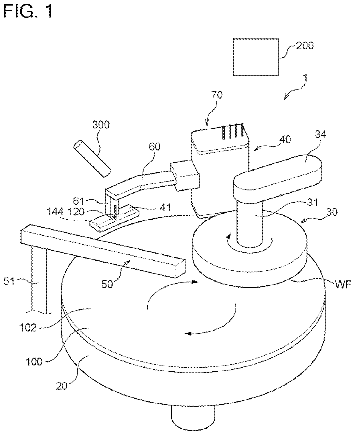
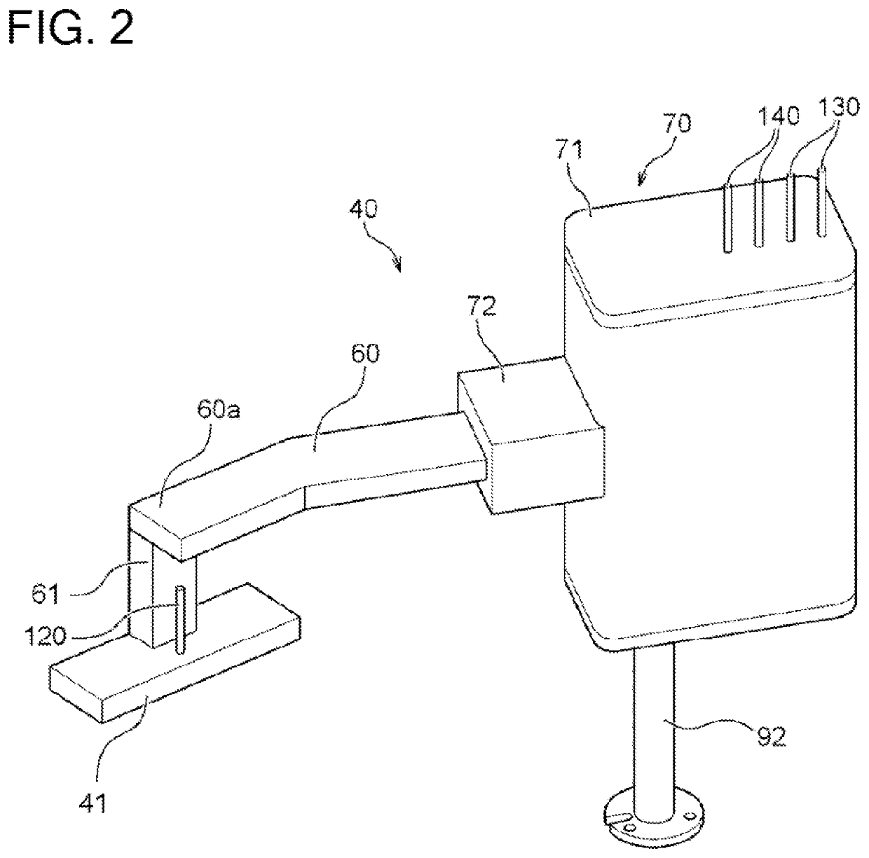
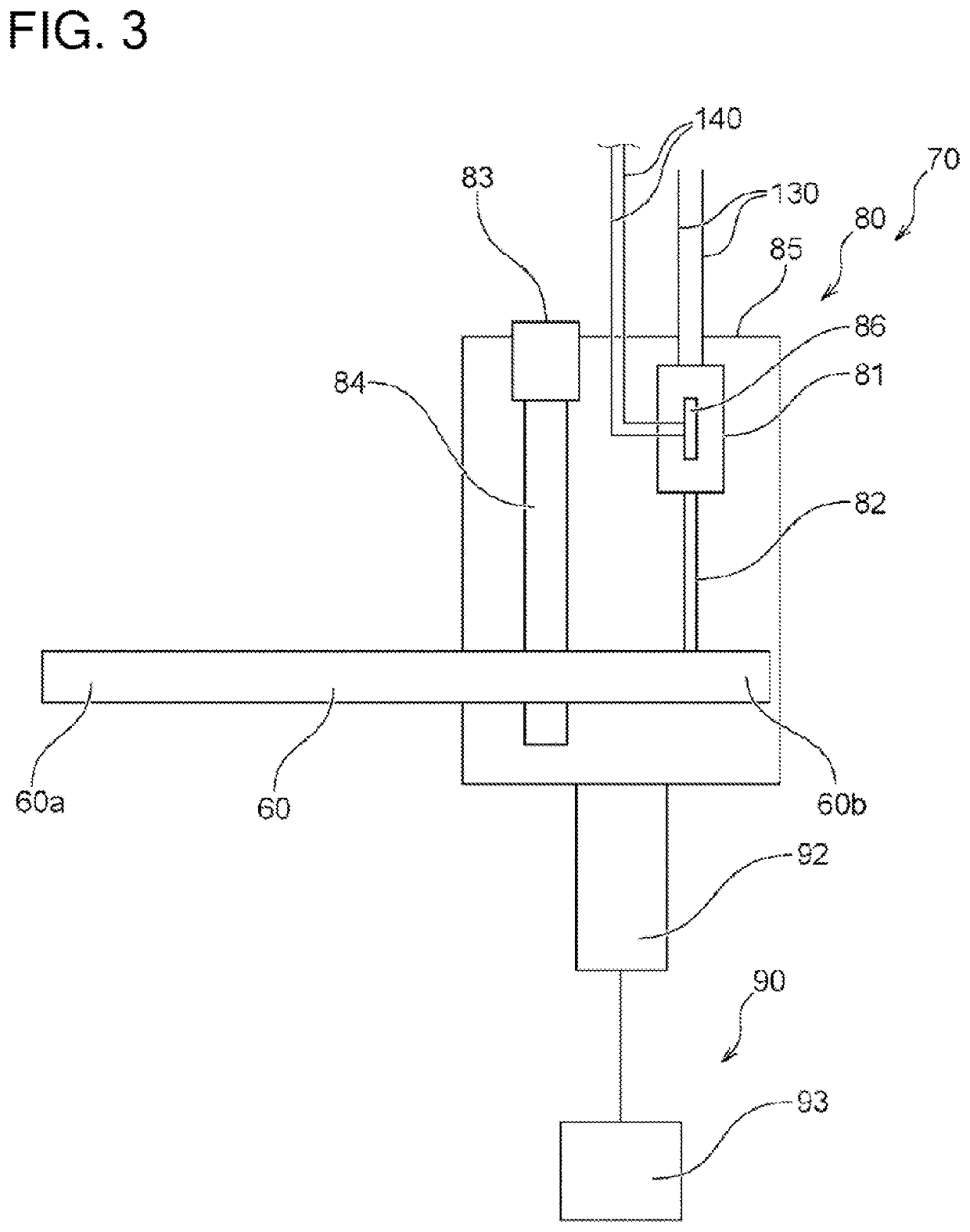
[0133]FIG. 24 is a diagram illustrating the schematic configuration of a polishing apparatus according to one embodiment of the present disclosure. A polishing apparatus 1 of the embodiment is configured to polish a substrate WF such as a semiconductor wafer as an object to be polished by using a polishing pad 100 having a polishing surface 102. As illustrated, the polishing apparatus 1 includes a polishing table 20 configured to support the polishing pad 100 and a top ring (substrate holder) 30 configured to hold the substrate and press the substrate against the polishing surface 102 of the polishing pad 100. The polishing apparatus 1 additionally includes a polishing solution supply system 40-1 configured to supply a polishing solution (slurry) to the polishing pad 100 and an atomizer 50 configured to spray a liquid such as pure water and / or a gas such as nitrogen onto the polishing surface 102 so as to wash away the used slurry, the p...

second embodiment

[0186]FIG. 33 is perspective views illustrating a polishing solution supply mechanism 400-1 according to a second embodiment. FIG. 33(A) illustrates the polishing solution supply mechanism 400-1 with a main cover 510 and an auxiliary cover 520 mounted thereto. FIG. 33(B) illustrates the polishing solution supply mechanism 400-1 with removal of the auxiliary cover 520. FIG. 33(C) illustrates the polishing solution supply mechanism 400-1 with further removal of the arm 60. FIG. 34 is a plan view illustrating the polishing solution supply mechanism 400-1 with removal of the auxiliary cover 520.

[0187]This embodiment differs from the above embodiment by providing a cover 500-1 to cover the entire configuration including the polishing solution supply device 41-1 (the pad body 410 and the weights 423), the following mechanism 45 and the suspending mechanism 46, in place of the cover 430 provided to cover the pad body 410 and the weights 423 described above. The other configuration of this ...


PUM


Abstract

There is provided an apparatus for polishing, comprising a table configured to support a polishing pad; a polishing head configured to hold a substrate; and a polishing solution supply device configured to supply a polishing solution between the polishing pad and the substrate. The polishing solution supply device comprises a plurality of polishing solution supply ports arrayed in a direction intersecting with a rotating direction of the polishing pad in a state that the polishing solution supply device is placed on an upstream side in rotation of the polishing pad relative to the substrate. The polishing solution supply device supplies the polishing solution, such that the polishing solution supplied from the plurality of polishing solution supply ports has a predetermined flow rate distribution.

Description

TECHNICAL FIELD[0001]The present disclosure relates to an apparatus for polishing, a processing system, and a method of polishing.BACKGROUND ART[0002]In the manufacturing process of a semiconductor device, the planarization technology of the surface of the semiconductor device is of increasing significance. One known planarization technique is CMP (chemical mechanical polishing). This CMP uses a polishing apparatus to slide and polish a substrate such as a semiconductor wafer against a polishing pad with supplying a polishing solution (slurry) containing abrasive grains of, for example, silica (SiO2) and / or ceria (CeO2) to the polishing pad.[0003]A polishing apparatus that performs a CMP process includes a polishing table configured to support a polishing pad, a polishing head configured to hold an object such as a substrate, and a polishing solution supply device configured to supply a polishing solution between the polishing pad and the substrate. This polishing apparatus causes t...

Claims


Application Information

Patent Timeline
Patent Type & Authority Applications(United States)
IPC IPC(8): B24B57/02B24B37/04
CPCB24B57/02B24B37/042B24B37/107B24B37/34B24B41/02H01L21/30625B24B37/04B24B37/30H01L21/304
Inventor MORIURA, TAKUYASOTOZAKI, HIROSHISONE, TADAKAZUITO, MASAYOSHIKOBATA, ITSUKIMATSUO, HISANORITERADA, TETSUYA
Owner EBARA CORP
Learn More