Prompt gamma monitor for hadron therapy

a gamma monitor and hadron technology, applied in the field of prompt gamma monitors, can solve the problems of gamma ray detectors, however bulky and expensive, and are too sensitive to the intense neutron flux produced in the targ

Active Publication Date: 2021-09-16
EBAMED SA
View PDF2 Cites 3 Cited by
  • Summary
  • Abstract
  • Description
  • Claims
  • Application Information

AI Technical Summary

Benefits of technology

The patent describes an improved imaging instrument that can continuously record the position and dose of irradiation to a patient during hadron therapy. This allows for real-time interactive corrections to the treatment plan. The instrument uses a dual-layer concept to effectively suppress false counts and improve the resolution of position measurement. Compared to existing systems, the instrument is compact and light, providing images of the radiation fields in real-time and facilitating on-line correction of motion artifacts. The instrument distinguishes hard photons from background neutron interactions and uses a neutron absorber to reduce the flux of incoming neutrons. These features improve the signal-to-noise ratio and help in ensuring accurate treatment outcomes.

Problems solved by technology

Gamma ray detectors are common instruments in particle and nuclear physics; they are however generally bulky and expensive due to the massive use of fast electronics used to record events.
Moreover, they are often too sensitive to the intense neutron flux produced in the target and to the neutron field present in the irradiation room.
There are also concerns on the radiation damage of sensitive electronics exposed to radiation.
Even more than for standard neoplasm treatments, this modality requires a precise knowledge of the beam position, distribution and penetration depth in the patient, and is complicated by the blurring due to the patient's breathing motion and heartbeats.
This can only be implemented if the time of the beam pulse is known either by direct measurement or using the information provided by the accelerator, thus imposing strict limits to the rate and bunch structure of the beam.

Method used


Image

  • Prompt gamma monitor for hadron therapy
  • Prompt gamma monitor for hadron therapy
  • Prompt gamma monitor for hadron therapy

Examples


Embodiment Construction

[0022]The invention will be better understood hereafter, with some non-limiting examples and with the following figures:

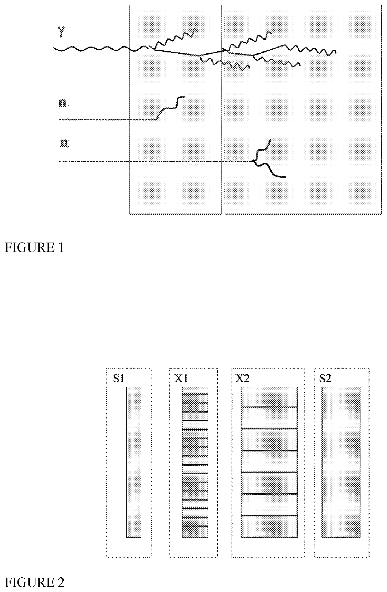
[0023]FIG. 1: Operating principle of the dual-layer Prompt Gamma Monitor (PG-MON) according to the invention, with two contiguous and independent detection modules. Prompt gammas from the beam-target interactions interact in the first module and generate an electromagnetic shower propagating to the second module until full absorption, (The number of gammas in a shower is exaggerated for illustration purposes). The prongs due to neutrons interactions remain instead confined in only one of the two modules.

[0024]FIG. 2: Block schematics of the PG-MON (elements not to scale). X1 and X2 are independent scintillating crystals assemblies; S1 and S2 are light sensors used to detect and localize the scintillation photons. In one of the preferred embodiments, sensors arrays are mounted on both sides of each crystal assembly.

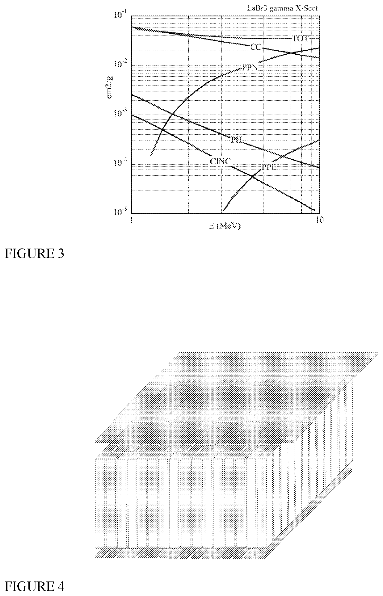
[0025]FIG. 3: Mass absorption coefficient of lantha...


PUM


Abstract

A medical imaging tool is described, capable of providing in real time 2-D images of the prompt gamma fields released during patient treatment. Owing to its millimetre position accuracy, the instrument is particularly suited for applications where a precise determination of the end-of-range (Bragg peak) of the beam is of paramount importance, as in cancerous and non-cancerous targets for treatment with ion beams and for the treatment of atrial fibrillation. With its unique dual-layer conception in coincidence, the instrument has high rejection ability against false neutron-generated counts, the principal source of background noise for in-beam dose monitoring. It can also provide a coarse measurement of the gamma incidence angle, permitting a correction of the parallax error, main source of dispersion for large area detectors employing collimators.

Description

FIELD OF THE INVENTION[0001]The present invention relates to the monitoring of prompt gamma rays that are generated during hadron therapies.BACKGROUND[0002]Radiation therapy with charged particles beams, also called ion beam therapy or hadron therapy, is a widely used method for the treatment of deep-seated tumors and other types of ailments in many hospital centers worldwide.[0003]Since the beginning of hadron therapy, many approaches have been explored to monitor the dose distribution during a therapeutic session, recording and analyzing the distribution of the secondary radiation fields resultant from the beam-patient interactions: charged particles, neutrons, positron-emitting isotopes, gamma rays. Of all yields, the a-priori best candidate for imaging are prompt gamma rays, in the energy range between one and ten MeV, for several reasons:[0004]The emission intensity is proportional to the product of the local fluence of the slowing ions by the nuclear prompt gamma cross-section...

Claims


Application Information

Patent Timeline
IPC IPC(8): G01T1/29G01T1/20A61N5/10G01T1/02
CPCG01T1/29G01T1/023A61N5/1048G01T1/20
Inventor SAULI, FABIOGARONNA, ADRIANO
Owner EBAMED SA
Why Eureka
Try Eureka