

Microelectromechanical microphone with reduced overall size
- Summary
- Abstract
- Description
- Claims
- Application Information
AI Technical Summary
Benefits of technology
Problems solved by technology
Method used
Image

Examples
Embodiment Construction
[0056]The same references are used to describe elements having substantially the same structure or substantially the same function.
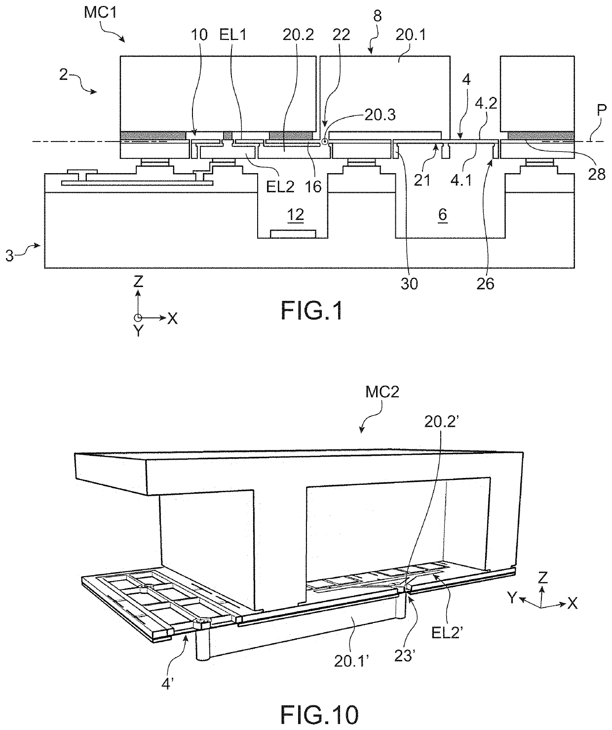
[0057]In FIG. 1 an exemplary embodiment of a microphone MC1 according to the invention can be seen.
[0058]The microphone includes a microphone unit 2 and a cover 3.
[0059]Microphone unit 2 contains the elements for sensing and measuring the pressure variation. This microphone unit is made from a first substrate, the cover is made from a second substrate and the microphone is obtained directly after assembling the first and second substrates without requiring any additional step.
[0060]The microphone unit comprises a piston 4 or element sensitive to pressure variations, means 10 for measuring the displacement of the piston, means 8 for mechanically transmitting the displacement of the piston to the measurement means and an sealed insulation element between the part for sensing the pressure variation and the part for measuring this pressure variation.
[0061]In...
PUM
 Abstract
Description
Claims
Application Information