Fluid-flow machine with high-pressure and low-pressure regions

Inactive Publication Date: 2005-02-08
SIEMENS AG
View PDF15 Cites 2 Cited by
  • Summary
  • Abstract
  • Description
  • Claims
  • Application Information

AI Technical Summary

Benefits of technology

The compact design of the fluid-flow machine leads to further advantages in production, which lead to material and time savings. The material and time saving may be attributed, inter alia, to a design of the components in a reduced form. The use of less material leads to components of smaller mass and thereby to better start-up and operating behavior; in particular the reduction in size of the last blade stages is advantageous here.
Due to the smaller mass, the moment of inertia of the rotor changes. As a result, the start-up time is reduced.
It is advantageous to provide the backflow passage with an axial compensator for compensating for thermal expansions. Temperature-induced outer casing stresses are thereby avoided. The axial compensator, for example, may include a bellows or the like.
A considerable advantage in this case results from the simple cost-effective integration in the casing.
To reduce leakages between the outer casing ends and the rotor, sealing shells with labyrinth seals or the like are arranged.
The fluid-flow machine preferably has an inflow region in which the flow medium is expanded in an adjoining expansion region by a control stage. The pressure of the flow medium in the expansion region is expanded to a wheel space pressure by a control stage. This control method provides for a rapid and precise means of controlling the fluid-flow machine and leads to good operating behavior.

Problems solved by technology

Physical limits (e.g. strength) are encountered when realizing the flow area and this involves considerable construction outlay.
A disadvantage with these known embodiments having a high-pressure expansion region is that superheated steam comes in contact with the interior of a turbine end.
In this case, the introduction of the sealing shell steam into the blading regions leads to asymmetrical casing heating at the casing circumference, and this asymmetrical casing heating results in thermal stresses and deformations, i.e. distortion of the casing, which may possibly lead to grazing of blades on the casing.

Method used


Image

  • Fluid-flow machine with high-pressure and low-pressure regions
  • Fluid-flow machine with high-pressure and low-pressure regions
  • Fluid-flow machine with high-pressure and low-pressure regions

Examples


Embodiment Construction

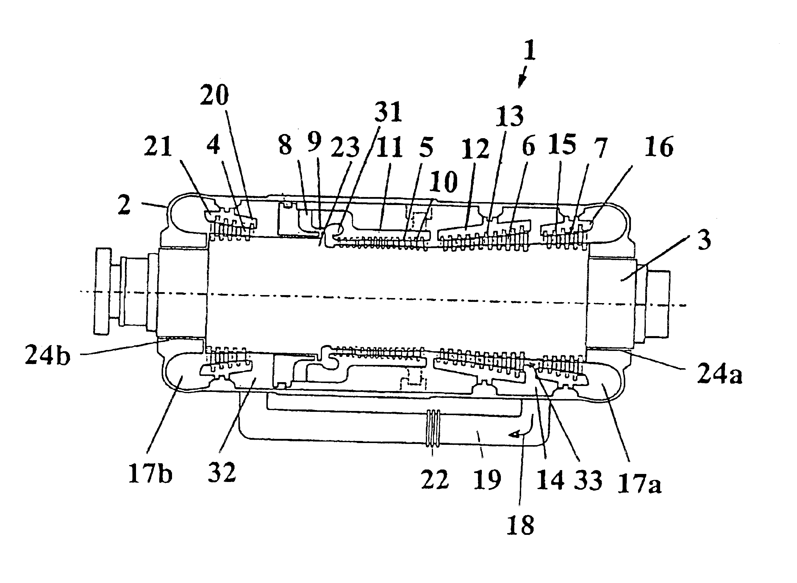
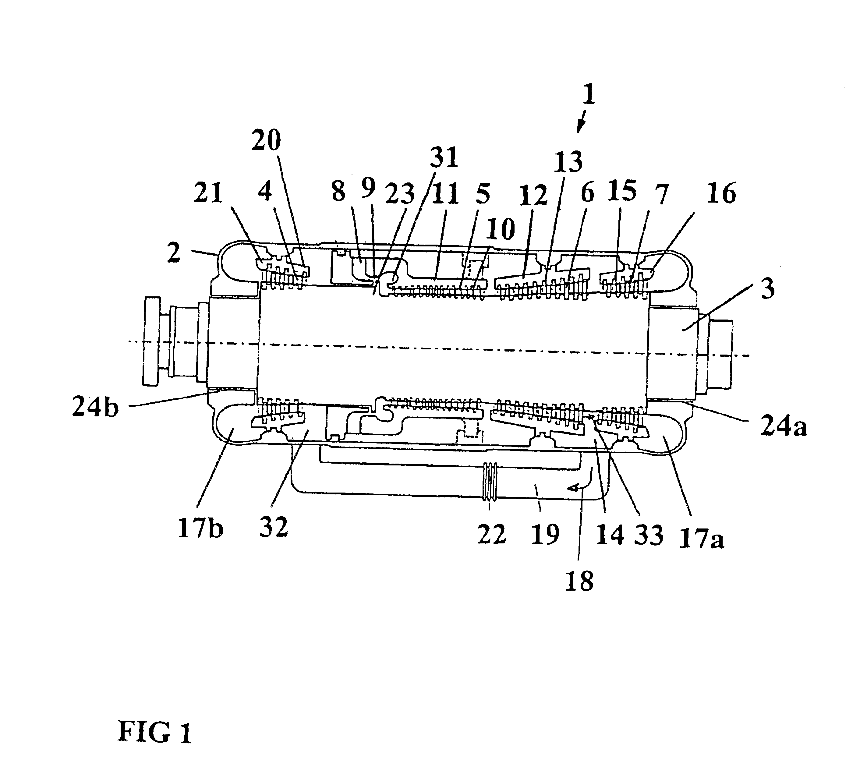
FIG. 1 shows a schematic longitudinal section through a fluid-flow machine 1 having an outer casing 2, a plurality of inner casings 11, 12, 16, 21 and a rotor 3. Four blade regions 4, 5, 6, 7 are arranged on the rotor 3. In this exemplary embodiment, the four blade regions are divided into two inner blade regions 5, 6 and two outer blade regions 4, 7. The two outer blade regions 4, 7 are arranged in opposition to one another and point away from the inner blade regions 5, 6.

Upstream of the first inner blade region 5, an inflow opening 8 is contained in the outer casing. A control stage 9 is provided starting from the inflow opening 8 in the direction of the first inner blade region 5. An expansion region 31 follows the control stage 9 in the direction of the first inner blade region 5. In the exemplary embodiment presented, guide blades 10 are attached to the inner casing 11 in the first inner blade region 5.

Following the first inner blade region 5 is a further inner blade region 6. ...


PUM


Abstract

A fluid-flow machine includes an outer casing having a rotationally mounted rotor with three blade regions. The blade regions are divided into an inner blade region and two outer blade regions, the two outer blade regions pointing outward toward the outer casing end. The fluid-flow machine includes one or more outlet openings, via which the flow medium is divided into two partial flows. The two partial flows then flow through the respective outer blade regions.

Description

The present application hereby claims priority under 35 U.S.C. §119 on European patent application number EP 02002719.9 filed Feb. 6, 2002, the entire contents of which are hereby incorporated herein by reference.FIELD OF THE INVENTIONThe invention generally relates to a fluid-flow machine which includes a casing. Preferably, the casing includes a rotationally mounted rotor with three blade regions which are fluidically connected. It also generally relates to a method of operating the fluid-flow machine as a steam turbine.BACKGROUND OF THE INVENTIONKnown fluid-flow machines which have a high-pressure and a low-pressure-steam region may be of single-cylinder or two-cylinder construction. Such fluid-flow machines, in particular steam turbines, are shown in 1997P03012 DE. The two-cylinder design does not belong to the technical field of the present invention and is therefore not described in more detail. The single-cylinder design consists of a rotor having two single-flow blade region...

Claims


Application Information

Patent Timeline
IPC IPC(8): F01D1/00F01D1/02F01D1/04F01D25/00F01D25/16F01D25/24F01D25/26F04D27/00F04D29/10F04D29/32
CPCF01D1/04F01D1/023
Inventor KLAUS, GERHARDSTEPHAN, INGO
Owner SIEMENS AG
Why Eureka
Try Eureka