Image processing system, display device, image processing method, method for generating trained model, and dataset for learning

a technology for image processing and display devices, which is applied in image analysis, image enhancement, constructions, etc., can solve problems such as incorrectly specifying the position of dump bodies and ruts on ground surfaces, and achieve accurate specification of the position of parts of drop targets

Active Publication Date: 2021-09-23
KOMATSU LTD
View PDF0 Cites 5 Cited by
  • Summary
  • Abstract
  • Description
  • Claims
  • Application Information

AI Technical Summary

Benefits of technology

[0007]According to the above aspect, it is possible to accurately specify the position of a part of a drop targ

Problems solved by technology

In a case where a road is not paved at a site where a loading machine is present, a rut may be generated on a ground surface.
Therefore, in a case where the position of the dump body of the dump truck is specified from the captured

Method used


Image

  • Image processing system, display device, image processing method, method for generating trained model, and dataset for learning
  • Image processing system, display device, image processing method, method for generating trained model, and dataset for learning
  • Image processing system, display device, image processing method, method for generating trained model, and dataset for learning

Examples


first embodiment

[0029]Hereinafter, embodiments will be described in detail with reference to drawings.

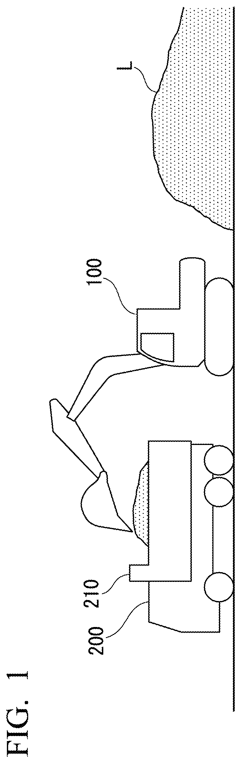
[0030]FIG. 1 is a diagram showing a configuration of a loading place according to one embodiment.

[0031]At a construction site, a hydraulic excavator 100 which is a loading machine and a dump truck 200 which is a transport vehicle are provided. The hydraulic excavator 100 scoops a transport object L such as earth from the construction site and loads the transport object on the dump truck 200. The dump truck 200 transports the transport object L loaded by the hydraulic excavator 100 to a predetermined earth removable place. The dump truck 200 includes a dump body 210 which is a container for accommodating the transport object L. The dump body 210 is an example of a drop target on which the transport object L is dropped. The construction site is an example of a site. The site is a location at which the loading machine works.

Configuration of Hydraulic Excavator

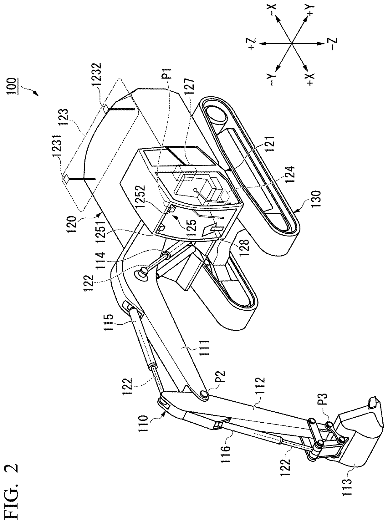
[0032]FIG. 2 is an external view of a hydr...

second embodiment

[0096]Hereinafter, a second embodiment will be described with reference to the drawings. The control device 127 according to the first embodiment uses the feature point specifying model M1 and the similarity specifying model M2 to respectively specify the positions of the feature points on the right-eye image and the positions of the feature points on the left-eye image. On the contrary, the control device 127 according to the second embodiment uses one trained model to specify the positions of the feature points on the right-eye image and the positions of the feature points on the left-eye image.

Configuration of Control Device

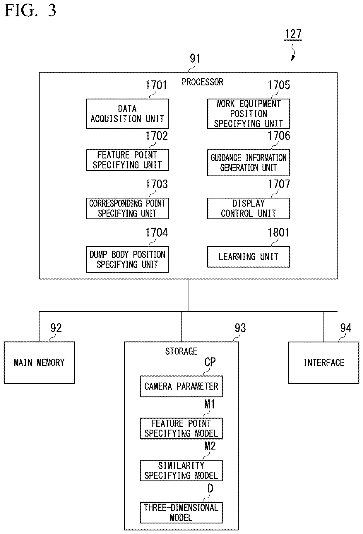
[0097]FIG. 11 is a schematic block diagram showing a configuration of a control device according to the second embodiment.

[0098]The processor 91 according to the second embodiment includes a stereo feature point specifying unit 1708 instead of the feature point specifying unit 1702 and the corresponding point specifying unit 1703 according to the first embodim...

third embodiment

[0111]Hereinafter, a third embodiment will be described with reference to drawings. The control device 127 according to the first embodiment and the second embodiment specifies the positions of the feature points on the image by using the trained model and specifies the three-dimensional positions of the feature points by triangulation based on the specified positions. On the contrary, the control device 127 according to the third embodiment specifies the three-dimensional positions of the feature points by using a trained model.

Configuration of Control Device

[0112]FIG. 14 is a schematic block diagram showing a configuration of a control device according to the third embodiment.

[0113]The processor 91 according to the third embodiment includes a three-dimensional feature point specifying unit 1709 instead of the feature point specifying unit 1702 and the corresponding point specifying unit 1703 according to the first embodiment. The storage 93 stores a three-dimensional feature point...


PUM


Abstract

An image processing system includes a data acquisition unit and a position specifying unit. The data acquisition unit acquires a captured image showing a drop target of a work machine in which a transport object is dropped. The position specifying unit specifies a position of a predetermined part of the drop target shown in the captured image based on the captured image and a position specifying model. The position specifying model is a trained model, which outputs a position of a predetermined part of a drop target shown in an image when the image is input. A display device may display information regarding the position of the predetermined part of the drop target of the transport object specified by the image processing system.

Description

[0001]This application is a U.S. National stage application of International Application No. PCT / JP2019 / 028510, filed on Jul. 19, 2019. This U.S. National stage application claims priority under 35 U.S.C. § 119(a) to Japanese Patent Application No. 2018-163670, filed in Japan on Aug. 31, 2018, the entire contents of which are hereby incorporated herein by reference.BACKGROUNDField of the Invention[0002]The present invention relates to an image processing system, a display device, an image processing method, a method for generating a trained model, and a dataset for learning.Background Information[0003]Japanese Unexamined Patent Application, First Publication No. 2000-192514 discloses a technique of extracting an edge from an image captured by an imaging device provided in a hydraulic excavator to specify the position of a dump body of a dump truck.SUMMARY[0004]In a case where a road is not paved at a site where a loading machine is present, a rut may be generated on a ground surface...

Claims


Application Information

Patent Timeline
IPC IPC(8): E02F9/26G06T7/00G06T7/73
CPCE02F9/26G06T7/0004G06T7/73G06T2207/30164G06T2207/10012G06T2207/20084G06T2207/20081E02F3/439E02F9/261E02F9/264E02F9/123
Inventor KAWAMOTO, SHUN
Owner KOMATSU LTD
Why Eureka
Try Eureka