
Precision, constant-flow reciprocating pump

a technology of reciprocating pump and constant flow, which is applied in the direction of pump, positive displacement liquid engine, machine/engine, etc., can solve the problems of affecting the accuracy of the pump, and plastic parts reducing the life of the pump head

Pending Publication Date: 2021-09-23
SWISSINNOV PROD SARL
View PDF3 Cites 0 Cited by
  • Summary
  • Abstract
  • Description
  • Claims
  • Application Information

AI Technical Summary

Benefits of technology

The present invention is a pump that is efficient, made up of very few parts, and has a low production cost. It is designed to pump and dispense liquids, viscous products, and gases with even varying flow rates. It solves previous problems by controlling the movements of the pistons and valves with a single rotor outside the interchangeable fluidic module. This allows for accurate and durable pumps with high pressures. The production of the pump head is also more economical because it has a reduced number of elements in contact with the fluid.

Problems solved by technology

The main problem encountered by this system stems from the fact that the driving elements of the pistons are incorporated in the interchangeable fluidic module, made of inexpensive plastic, affecting the accuracy of the pump given that the stroke of the pistons depends on the quality of the movement imparted to the guiding axes along the cam.
The wear of the plastic parts reduces the life of the pump head which, in some cases, even culminates in the breaking of the cam when the heating originating from the friction of the axes along the cam is prolonged.
The lateral supports of the cam can also be deformed or even break when the pressure in the pump increases, which limits the use of this type of pump for applications requiring pressures greater than a few bar.
Another disadvantage is that the seal between the rotor and the stator is made using a seal of circular form which undergoes one-way circular friction during the operation of the pump, thus creating a significant localized heating on the rotor which can rapidly be deformed and render the pump inoperative.

Method used


Image

  • Precision, constant-flow reciprocating pump
  • Precision, constant-flow reciprocating pump
  • Precision, constant-flow reciprocating pump

Examples


Embodiment Construction

[0006]The present invention relates to an efficient pump composed of a reduced number of parts with very low production cost for the pumping and dosing of liquids, viscous products or gases with even variable flow rate.

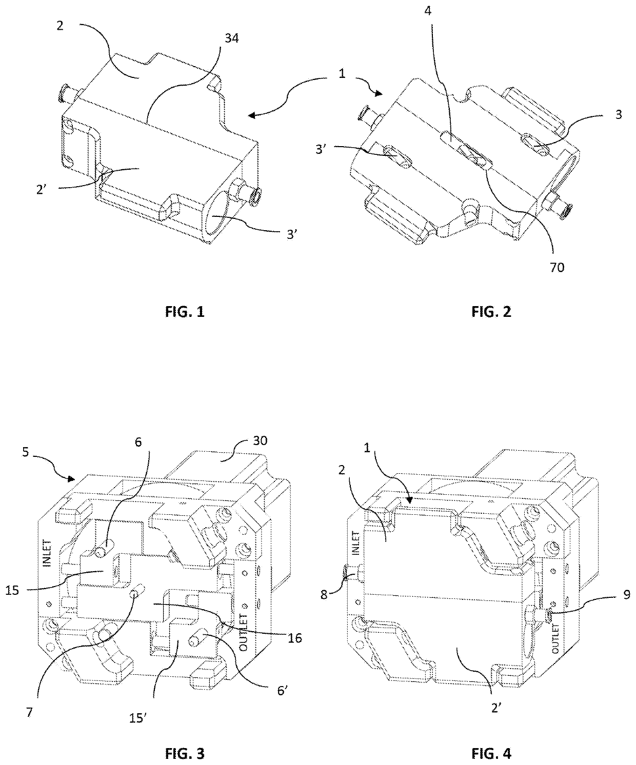
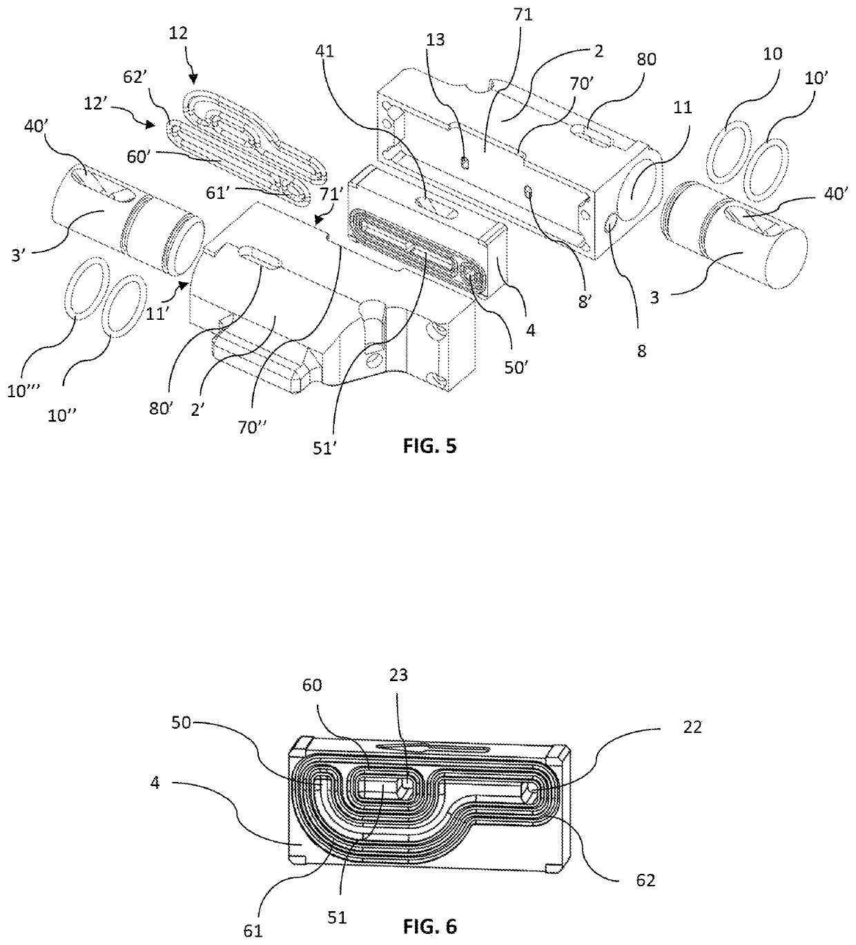
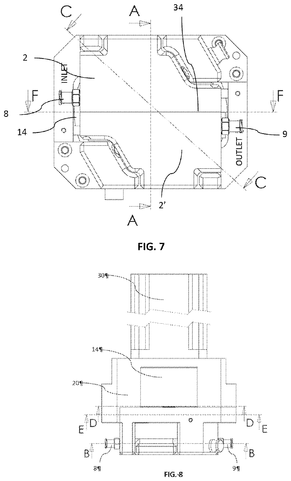
[0007]This invention solves the problems explained previously, by controlling the movements of the pistons and of the switching element of the valves, preferably linearly and parallel to one another, by a single rotor positioned in a driving mechanism of the pump outside the interchangeable fluidic module. All the movements of the driving mechanism are produced by robust and accurate standard guiding elements, reliably ensuring a guiding of the pistons and able to withstand very high pressures in the pump. It is thus possible to produce a pump with even variable flow rate that is very accurate, durable and suited to applications requiring pressures greater than a few bar.

[0008]The production of the pump head is also more economical because the latter advantageously co...


PUM


Abstract

A pump having two pistons which are driven by a cam belonging to an external rotor and which are inserted into two cylinder blocks mounted parallel to each other in such a way as to form two opposite, parallel, eccentric pump chambers The pump chambers have at least one inlet port through which liquid is drawn into the pump chambers during the fill stroke of the pistons, and then expelled from the pump chambers during the discharge stroke of the pistons to at least one outlet port, the outflow rate of which is constant and even.

Description

[0001]The invention relates to a volumetric pump consisting of two pistons for the accurate and variable flow-rate dispensing of liquid, of medicine, of food, of detergent, of cosmetic product, of chemical compound or any other type of fluid, gel or gas.PRIOR ART[0002]There are various pumps with a cam as described in the patent PCT / IB2013 / 059393 in which the operating principle consists in driving a rotor containing two cylinders and pistons for obtaining an even flow rate.[0003]In the patent PCT / IB2013 / 059393, the driving of each piston is done by means of an axis guided by one or both of the ends of the axis running through a cam placed in the stator and optionally by an opposing similar cam in the cover. This mechanism is incorporated in the fluidic module or interchangeable pump head, made of plastic to be disposable.[0004]The main problem encountered by this system stems from the fact that the driving elements of the pistons are incorporated in the interchangeable fluidic modu...

Claims


Application Information

Patent Timeline
IPC IPC(8): F04B1/02F04B7/00
CPCF04B1/02F04B7/0053F04B7/003F04B7/0069F04B7/0015F04B9/047F04B13/00F04B1/03F04B9/04F04B23/06F04B41/06
Inventor JUNOD, FLORENTNAVARRO, THIERRY
Owner SWISSINNOV PROD SARL
Learn More