
Method and system for orifice control of valve pressure drop

a technology of orifice control and pressure drop, which is applied in the direction of fractional distillation, separation process, chemistry apparatus and processes, etc., can solve the problems of affecting the capacity and efficiency of the tray, affecting the stability and consistency of the column equipped with structured packing, and a large degree of weeping

Pending Publication Date: 2021-09-30
SULZER MANAGEMENT AG
View PDF0 Cites 0 Cited by
  • Summary
  • Abstract
  • Description
  • Claims
  • Application Information

AI Technical Summary

Benefits of technology

The patent text is about a new type of tray for use in chemical-process columns that improves the efficiency of mixing lighter and heavier fluids. This is achieved by using a valve tray with a circumferential vane that helps direct the ascending vapor directly downward onto the tray surface, resulting in better mixing and improved contact efficiency between the two fluids. The valve also promotes intimate mixing and mass transfer between the two fluids by deflecting the lighter fluid in a perpendicular direction to the flow of the heavier fluid. Overall, this valve tray design improves the efficiency of the chemical process.

Problems solved by technology

Some contact devices, such as trays, are characterized by relatively high pressure drop and relatively high fluid hold-up.
However, these very properties at times make columns equipped with structured packing difficult to operate in a stable, consistent manner.
It is the active area of the tray, however, which is of concern.
A small degree of weeping is normal in trays while a larger degree of weeping is detrimental to the capacity and efficiency of a tray.
The concentration-difference between the lighter fluid and the heavier fluid can be effected in many ways; some reducing efficiency.
This lighter fluid is not firmly held and is released within the downcomer, and, in fact, the majority of said lighter fluid must be released otherwise the downcomer cannot accommodate the heavier fluid / lighter fluid mixture and will flood, thus preventing successful tower operation.
In many cases, such opposition leads to poor tower operation and premature flooding.
A drawback of the commercially available valve trays is that their contact efficiency, i.e. the mixing efficiency of the lighter fluid, in particular gas or vapor, and the heaver fluid, in particular liquid, is in need of improvement.

Method used


Image

  • Method and system for orifice control of valve pressure drop
  • Method and system for orifice control of valve pressure drop
  • Method and system for orifice control of valve pressure drop

Examples


Embodiment Construction

[0061]Various embodiments will now be described more fully with reference to the accompanying drawings. The disclosure may, however, be embodied in many different forms and should not be construed as limited to the embodiments set forth herein.

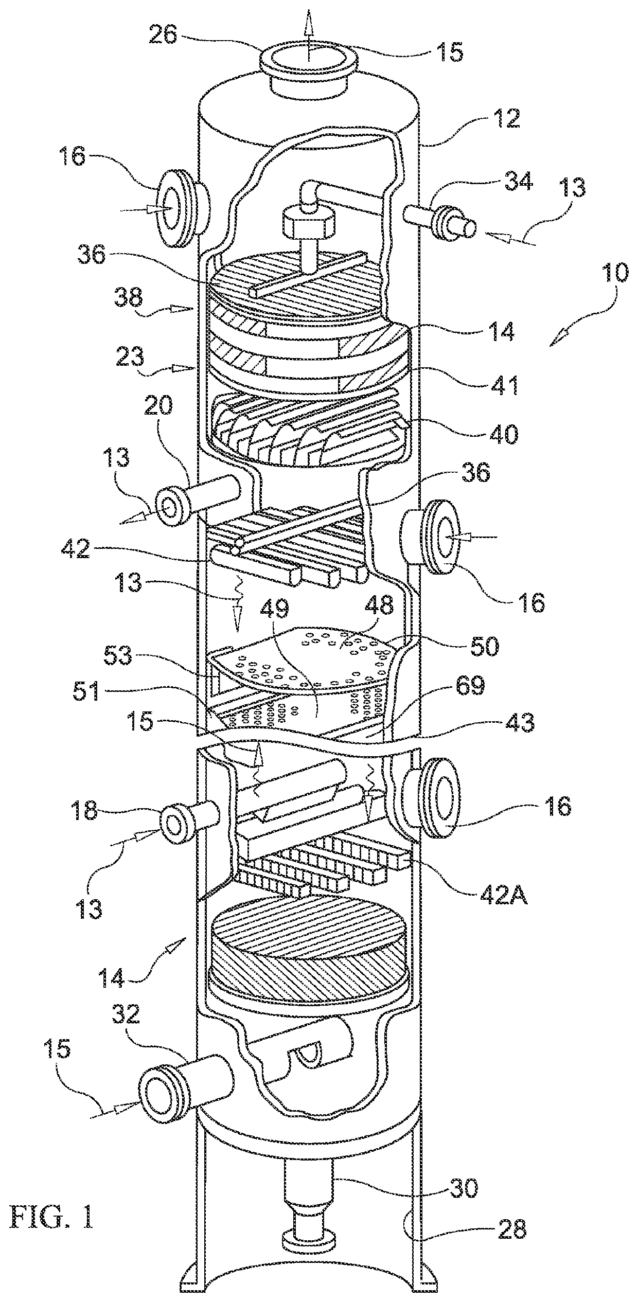
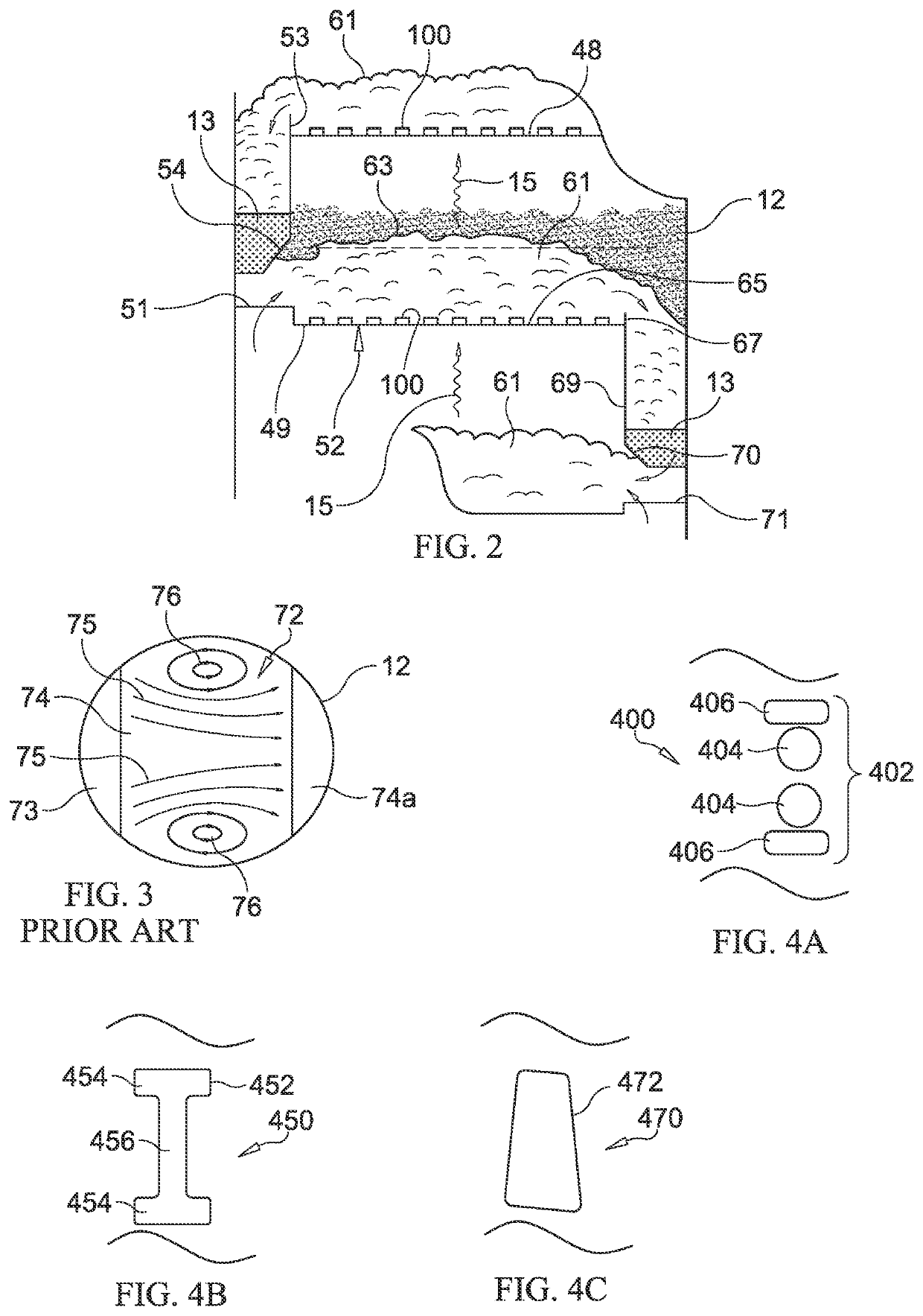
[0062]Referring first to FIG. 1, there is shown a fragmentary, perspective view of an illustrative packed exchange tower or column with various sections cut away for showing a variety of tower internals and the utilization of one embodiment of an improved high-capacity tray assembly. The exchange column 10 of FIG. 1 comprises a cylindrical tower 12 having a plurality of packing bed layers 14 and trays disposed therein. A plurality of manways 16 is likewise constructed for facilitating access to the internal region of the tower 12. Also provided are side stream draw-off line 20, heavier-fluid side feed line 18, and side stream lighter-fluid feed line or reboiler return line 32. A reflux return line 34 is provided atop the column 10.

[0063]In ope...


PUM


Abstract

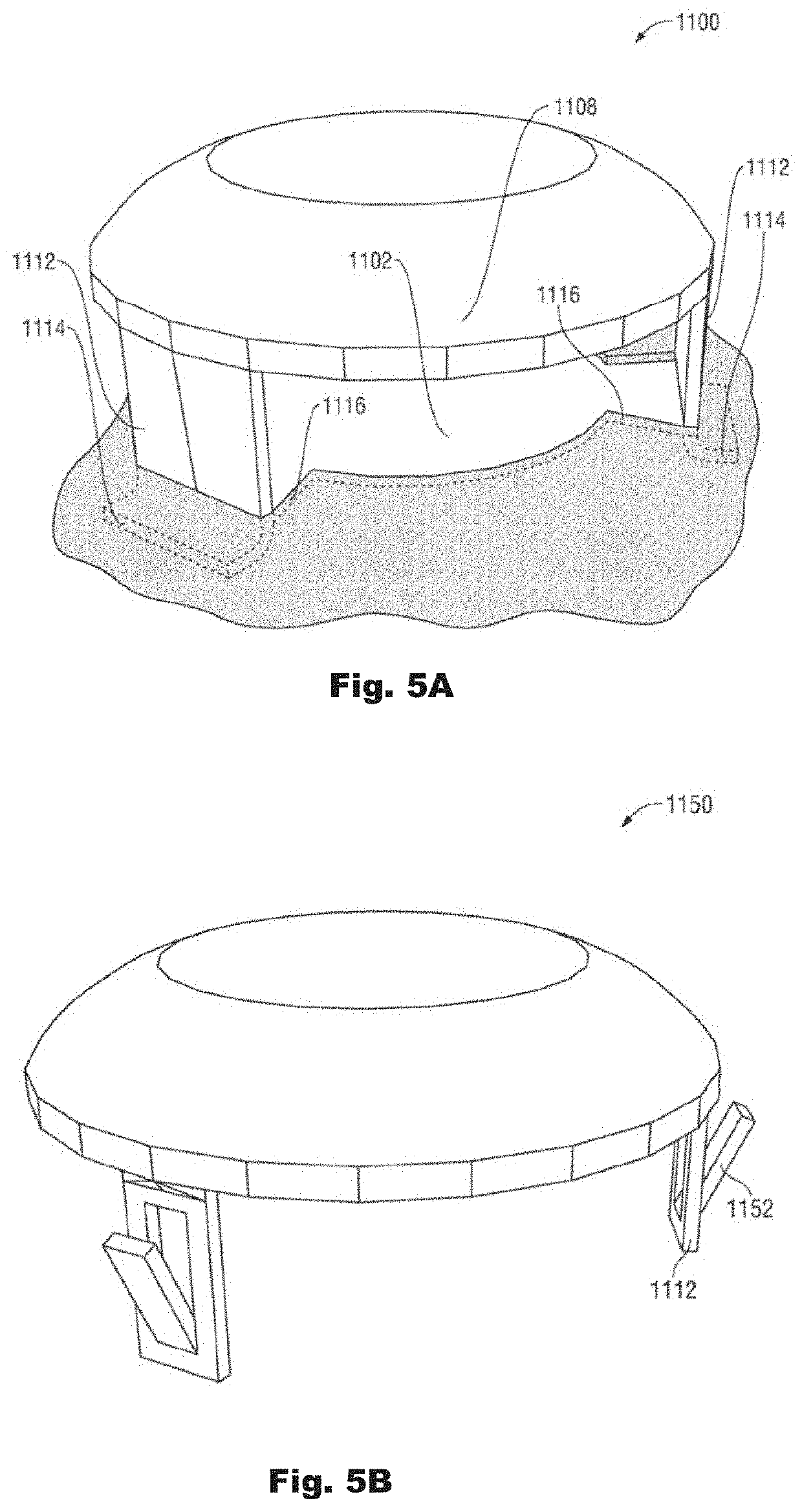
The present disclosure relates to a valve tray for use in a chemical process column. The valve tray includes a plurality of apertures formed therein. A plurality of valves are maintained in a spaced relationship relative to individual apertures of the plurality of apertures. An area of the individual apertures is less than an area of individual valves of the plurality of valves.

Description

CROSS-REFERENCE TO RELATED APPLICATIONS[0001]This application is a continuation-in-part application of U.S. patent application Ser. No. 15 / 881,204, filed on Jan. 26, 2018. U.S. patent application Ser. No. 15 / 881,204 is a continuation-in-part application of U.S. patent application Ser. No. 14 / 822,637, filed on Aug. 10, 2015.BACKGROUNDField of the Invention[0002]The present disclosure relates to fluid-fluid contacting trays. In particular, the present disclosure relates to an improved fluid dispersion device and tray assembly incorporating fixed valves including “snap-in” field replacement valve configurations for use in conjunction with an array of tray deck orifices of having a selectively reduced size.Background Information[0003]This section provides background information to facilitate a better understanding of the various aspects of the disclosure. It should be understood that the statements in this section of this document are to be read in this light, and not as admissions of p...

Claims


Application Information

Patent Timeline
IPC IPC(8): B01D3/16B01D3/20
CPCB01D3/163B01D3/205B01D3/324
Inventor FLEMING, PHILLIP BRADLEYBURTON, LARRY W.BINKLEY, MICHAEL J.
Owner SULZER MANAGEMENT AG
Learn More