
Projection

Pending Publication Date: 2021-09-30
DUALITAS LTD
View PDF0 Cites 0 Cited by
  • Summary
  • Abstract
  • Description
  • Claims
  • Application Information

AI Technical Summary

Benefits of technology

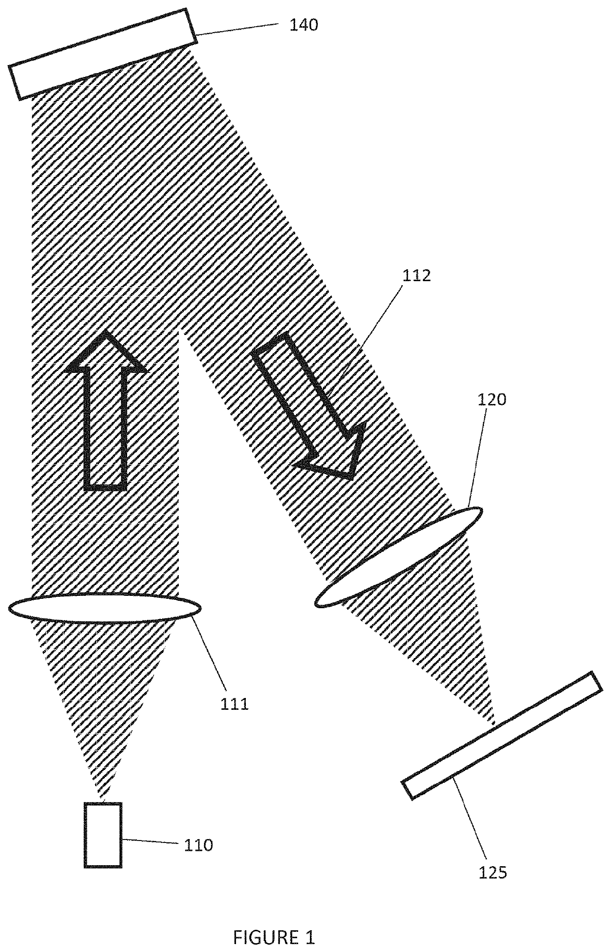
The inventor has found that in holographic projection using off-axis illumination of the display device and an optical element (such as a Fourier or Fresnel transform), tilting the display plane relative to the display device by an angle less than the angle of incidence of light on the display device can minimize the size of holographic image spots in the replay field. This is beneficial for a display device because smaller image spats are advantageous. The inventor has also found that when the first optical power is equal to the second optical power, the size of the image spots is minimized when there is a relative tilt between the display device and the display plane of half the second angle. The second optical power can be adjusted to change the relative tilt between the display device and the display plane.

Problems solved by technology

However, the inventor has actually found that with holographic projection this geometry gives rise to sub-optimal holographic reconstruction because there is an adverse effect on the size of the image spots formed by the holographic process—particularly, the image spots at the edge of the holographic replay field.

Method used


Image

  • Projection
  • Projection
  • Projection

Examples


example

[0115]The results set out in Tables 2 to 7 are achieved in the cases shown in Table 1. The spatial light modulator displays a diffractive pattern comprising a hologram and a software lens, without a grating function. The optical axis of the physical / projection lens is colinear with the projection axis between the spatial light modulator and the light-receiving surface. Thus, the plane of the physical lens is perpendicular to the projection axis. Accordingly, the plane of the spatial light modulator is tilted relative to the plane of the projection lens by θ and the plane of the light-receiving surface is tilted relative to the plane of the projection lens by α. The angles θ and α shown in Table 1 are angles in degrees to the normal of the plane of the spatial light modulator and light-receiving surface, respectively. The relative angle is the difference (in degrees) of the angle of the plane of the spatial light modulator relative to the angle of the plane of the light-receiving sur...


PUM


Abstract

There is disclosed herein an image projector arranged to project an image onto a display plane. The image projector comprises a processing engine, a display device, an optical element and a light source. The processing engine is arranged to output a computer-generated diffractive pattern comprising a hologram of an image for projection and a lens function corresponding to a lens having a first optical power. The display device is arranged to display the computer-generated diffractive pattern. The optical element is disposed between the display device to the display plane. The optical element has second optical power. The light source is arranged to provide off-axis illumination of the display device in order to spatially-modulated light in accordance with the hologram and lens function. The lens function of the computer-generated diffractive pattern and the optical element collectively perform a hologram transform of the hologram such that a reconstruction of the image is formed on the display plane. The display device is tilted with respect to the optical element by a first angle greater than zero. The display plane is tilted with respect to the optical element by a second angle greater than zero. The second angle is less than the first angle.

Description

CROSS-REFERENCE TO RELATED APPLICATIONS[0001]This application claims the benefit of priority of United Kingdom Patent Application no. 2004305.5, filed Mar. 25, 2020, which is hereby incorporated herein by reference in its entirety.FIELD[0002]The present disclosure relates to a projector. More specifically, the present disclosure relates to an image projector such as a holographic projector and a holographic projection system. Some embodiments relate a method of reducing the size of the image spots in a holographic replay field and some embodiments relate to a method of increasing the resolution in a holographic replay field. Some embodiments relate to a head-up display.BACKGROUND AND INTRODUCTION[0003]Light scattered from an object contains both amplitude and phase information. This amplitude and phase information can be captured on, for example, a photosensitive plate by well-known interference techniques to form a holographic recording, or “hologram”, comprising interference fring...

Claims


Application Information

Patent Timeline
IPC IPC(8): G03H1/00G03B21/00
CPCG03H1/0005G03H2001/0224G03B21/005G03B21/142G03H1/0443G03H1/12G03H2001/045G03H1/0808G03H1/2202G03H1/2286G03H1/2294G03H2001/2218G03H2001/2223G03H2210/20G03H2222/46G02B27/0103G02B2027/0174G03H1/02G03H1/22G03H1/2205G03H2001/0216G03H2001/221G03H2001/2215G03H2001/2255G03H1/04G03H1/10G03H2223/14
Inventor CHRISTMAS, JAMIESON
Owner DUALITAS LTD
Learn More