Power supply system

a power supply system and power supply technology, applied in the direction of battery overcharge protection, safety/protection circuit, transportation and packaging, etc., can solve the problems of electrical storage device overcharge, etc., to prevent or reduce the overcharge of electrical storage device

Active Publication Date: 2021-10-14
DENSO CORP
View PDF3 Cites 1 Cited by
  • Summary
  • Abstract
  • Description
  • Claims
  • Application Information

AI Technical Summary

Benefits of technology

[0025]Specifically, in a power supply system including a voltage generator and an electrical storage device, it is necessary to raise an operating voltage generated by the voltage generator in accordance with an operating state of each of the first load and the second load. As a result, the electrical storage device may sometimes overcharge when the electrical storage device charges based on the raised voltage. In view of this, according to yet another aspect of the present disclosure

Problems solved by technology

In such a power supply system, when an abnormality occurs in a load performing an essential function to drive the vehicle, such as an electric brake, an electric steering device, etc., the function is entirely lost thereby stopping the vehicle.
However, the electrical storage device is likely to redundantly charge by receiving power supplied from the voltage generator.
Specifically, there can be a risk that the electrical storage device overcharges based on power supplied from the voltage generator.
In such a situation, if the switch is in the switched-off state, power supply to the second load is interrupted, thereby possibly stopping continuous operation of the second load.
Specifically, when the abnormality occurs in the first route, the inter-route switch is switched off and power is continuously supplied from the second power supply to the second load through the diode component of the switch, an amount

Method used


Image

  • Power supply system
  • Power supply system
  • Power supply system

Examples


Embodiment Construction

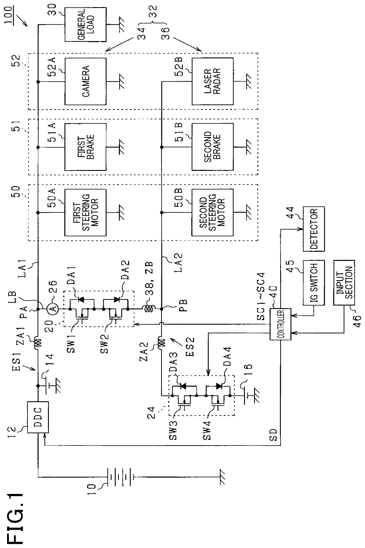
[0033]Referring now to the drawings, wherein like reference numerals designate identical or corresponding parts throughout the several views thereof, and to FIG. 1, a power supply system 100 is configured to supply power to a general load 30 and a specific load 32. The power supply system 100 includes a high-voltage secondary battery 10, a DC-DC (Direct Current to Direct Current) converter (hereinafter, simply referred to as a converter) 12, and a first low-voltage secondary battery 14. The power supply system 100 also includes a second low-voltage storage battery 16, a switch unit 20, and a controller 40.

[0034]The high-voltage secondary battery 10 has a rated voltage (for example, several hundred Volts) higher than rated voltages of the first low-voltage secondary battery 14 and the second low-voltage secondary battery 16. The high-voltage secondary battery may be composed of a lithium-ion secondary battery. The converter 12 converts electric power supplied from the high-voltage st...


PUM


Abstract

In a power supply system, a first route includes a first power supply connected to a first load. A second route includes a second power supply connected to a second load. A connection path connects the first and second routes at a connection point. The first power supply includes a voltage generator generating an operating voltage operating the first and second loads. The second power supply includes an electrical storage device charging based on power supplied from the voltage generator. A switching circuit includes a first switch having a diode component with an anode and a cathode being directed to the electrical storage device and the connection path, respectively, and is disposed between the connection point and the electrical storage device. A switch state controller outputs a switch-off command to the first switch when the electrical storage device is in the fully charged condition.

Description

CROSS-REFERENCE TO RELATED APPLICATION[0001]This patent application is based on and claims priority to Japanese Patent Application No. 2020-070355, filed on Apr. 9, 2020 in the Japan Patent office, the entire disclosure of which is hereby incorporated by reference herein.BACKGROUNDTechnical Field[0002]The present disclosure relates to a power supply system.Related Art[0003]A power supply system recently used in vehicles can control behavior of the vehicle. In such a power supply system, when an abnormality occurs in a load performing an essential function to drive the vehicle, such as an electric brake, an electric steering device, etc., the function is entirely lost thereby stopping the vehicle. To avoid entire loss of the function during driving of the vehicle when such an abnormality occurs, a conventional system employs first and second loads that perform a common function.[0004]For example, a conventional power supply system has a first route including a first power supply conn...

Claims


Application Information

Patent Timeline
IPC IPC(8): B60R16/033H02H3/08H02J1/10H02J7/14H02J7/34
CPCB60R16/033H02H3/08H02J7/34H02J7/1438H02J1/102B60R16/02H02J7/00302Y02T10/70H02J1/082H02J2310/40H02H3/16H02H7/268H02H7/28
Inventor MORITA, TETSUO
Owner DENSO CORP
Why Eureka
Try Eureka