
Anti-arc connector and pin array for a port

a technology of pin array and anti-arc connector, which is applied in the direction of coupling device connection, coupling contact member, two-part coupling device, etc., can solve the problems of affecting the reliability of the connection, the communication jack of the device is much more difficult, and the communication jack of the device is extremely time-consuming

Pending Publication Date: 2021-10-21
COMMSCOPE TECH LLC
View PDF3 Cites 0 Cited by
  • Summary
  • Abstract
  • Description
  • Claims
  • Application Information

AI Technical Summary

Benefits of technology

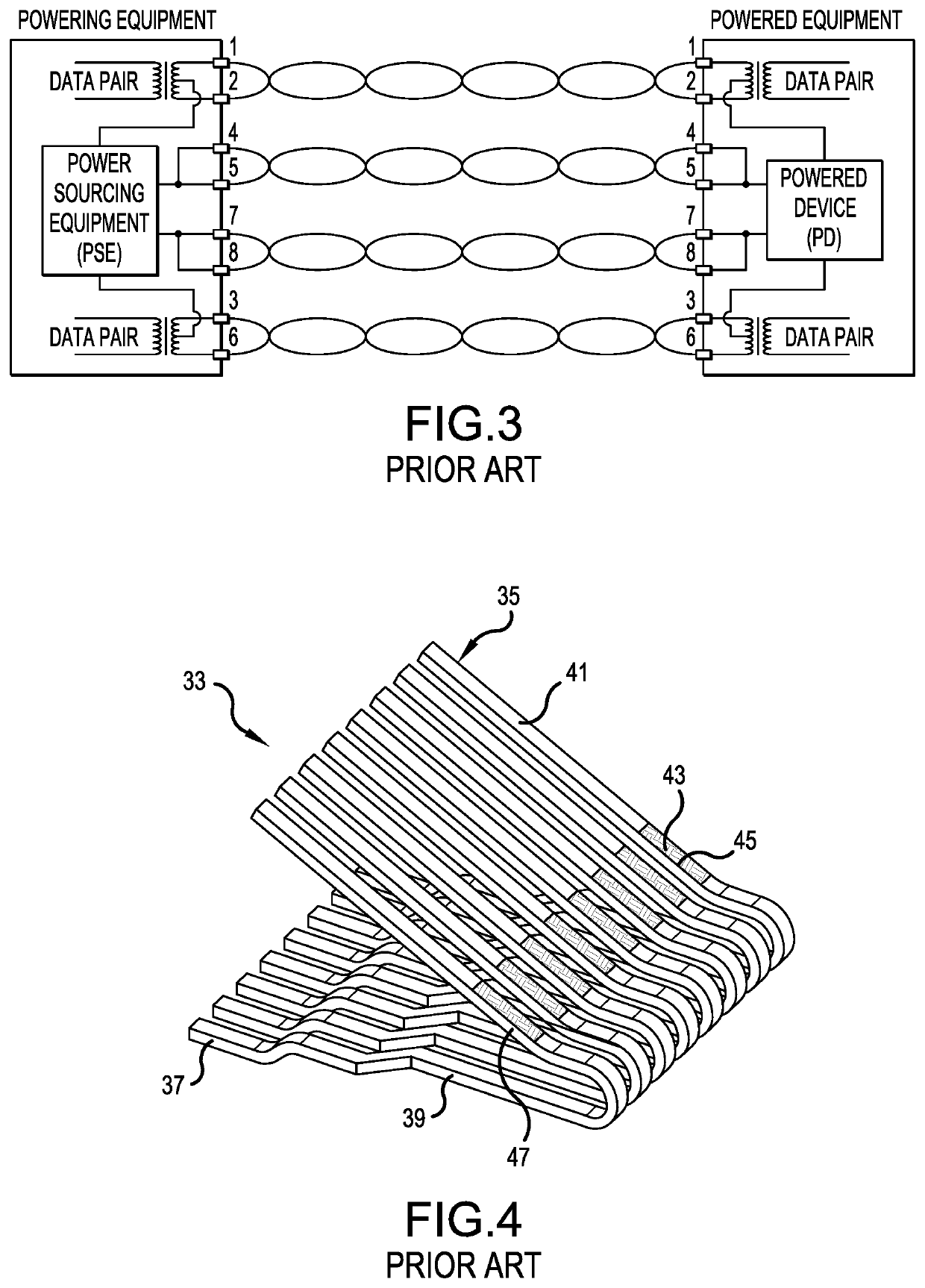
The patent is about a solution to prevent damage from electric sparks in new and future products. An upgraded RJ45 jack is recommended for this purpose. It can also be used as a retrofit solution for existing networks. Replacing the RJ45 communication jack in a device can be difficult and time-consuming. The patent provides a quick and easy way to replace the communication jack without having to open the device's housing or solder it onto a printed circuit board. This solution reduces the risk of damaging the device and ensures that no technician time is needed. The patent also discusses the issue of sparks and arcs when connecting or disconnecting devices from a network, and the recommended solution to address this issue.

Problems solved by technology

An upgraded RJ45 jack can also offer some limited benefits as a retrofit solution for existing networks.
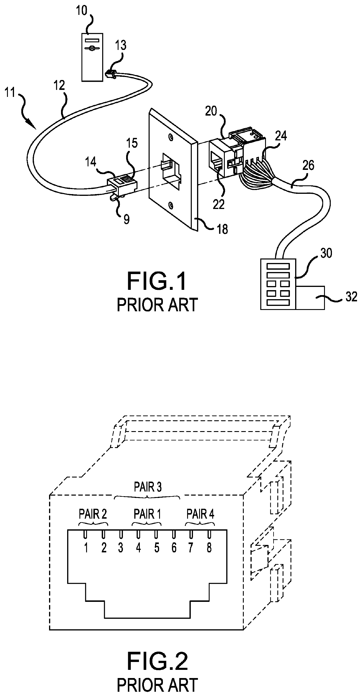
Upgrading the communication jack within a device, e.g. the portable hard drive 10, is much more difficult.
Hence, replacing the communication jack of a device is extremely time consuming and runs the risk of damaging the device.

Method used


Image

  • Anti-arc connector and pin array for a port
  • Anti-arc connector and pin array for a port
  • Anti-arc connector and pin array for a port

Examples


first embodiment

[0065]FIG. 7 is a front perspective view of a jackwire frame 113 for reducing damage due to sparks and arcs when disconnecting a PoE device 10 from the jack 101, in accordance with the present invention. In the embodiment of FIG. 7, the plurality of contact terminals 1-8 take the form of first through eighth jackwires A, B, C, D, E, F, G and H, which are formed of a resilient, conductive metal, such as resilient jackwires, sometimes called spring wires. The plurality of contact terminals A-H may be used to both receive or transmit communication signals as well as for transmitting power to the device 10.

[0066]For the purposes of explaining the operations of the present invention, at least two of the contact terminals are designated as primary contact terminals B, C, D, E, F and G which have first engagement portions b, c, d, e, f and g positioned at least a first distance from the plane 106 of the opening 105. The first engagement portions b, c, d, e, f and g of the at least two prim...

second embodiment

[0083]FIG. 8 is a front perspective view of a jackwire frame 121 for reducing damage due to sparks and arcs when disconnecting a PoE device 10 from the jack 101, in accordance with the present invention. FIG. 8 shows a three stage system. The primary contact terminals B, C, D, E, F and G have the same first bend angle and are spaced at about the same first distance from the plane 106 of the opening 105 and will disengage randomly at about the same time, during the first stage.

[0084]The secondary contact terminal H has a second bend angle greater than the first bend angle, which causes the second engagement portion h to be positioned at the second distance, less than the first distance, from the plane 106 of the opening 105. The second engagement portion h is the last portion of the secondary contact terminal H to make electrical contact with a corresponding blade of the plug 14 upon removal of the plug 14 from the opening 105 of the jack 101.

[0085]The plurality of contact terminals ...

third embodiment

[0089]FIG. 9 is a front perspective view of a jackwire frame 131 for reducing damage due to sparks and arcs when disconnecting a PoE device 10 from the jack 101, in accordance with the present invention. FIG. 9 also shows a three stage system with a different configuration, compared to FIG. 8. The primary contact terminals C, D, E and F have the same first bend angle and are spaced at about the same first distance from the plane 106 of the opening 105 and will disengage randomly at about the same time, during the first stage.

[0090]The secondary contact terminals G and H have a second bend angle greater than the first bend angle, which causes the second engagement portions g and h to be positioned at the second distance, less than said first distance, from the plane 106 of the opening 105. The second engagement portions g and h are the last portions of the secondary contact terminals G and H to make electrical contact with corresponding blades of the plug 14 upon removal of the plug ...


PUM


Abstract

To reduce sparks and arcing if an RJ plug is removed from an RJ jack while a PoE signal is present, the jack includes contact terminals for making electrical contact with blades of the plug. At least two primary contact terminals have first engagement portions positioned a first distance from the opening. At least one secondary and / or tertiary contact terminal has a second and / or third engagement portion, which is positioned less than the first distance from the opening. The engagement portions are the last portions of the contact terminals to make electrical contact with corresponding blades of the plug upon removal of the plug. At least one of the first engagement portions is formed of a first material different from a second material used to form at least one of the second or third engagement portions. One of the materials is formed to resist damage from sparks better than the other material.

Description

[0001]This application is a continuation of International Application No. PCT / US2020 / 015888, filed Jan. 30, 2020, which claims the benefit of U.S. Provisional Application No. 62 / 869,105, filed Jul. 1, 2019, and U.S. Provisional Application No. 62 / 799,692, filed Jan. 31, 2019, all of which are herein incorporated by reference.BACKGROUND OF THE INVENTION1. Field of the Invention[0002]The present invention relates to a jack and plug. More particularly, the present invention relates to a jack, such as an RJ-45, having improved electrical contacts within the jack to resist damage during unmating of a plug when a Power over Ethernet (PoE) signal is present. The present invention also relates to a plug, such as an RJ45 plug, having improved conductive blades to resist damage during unmating when a PoE signal is present.2. Description of the Related Art[0003]Computers, fax machines, printers and other electronic devices are routinely connected by communication cables to network equipment su...

Claims


Application Information

Patent Timeline
IPC IPC(8): H01R24/64H01R13/639H01R13/713H01R13/74
CPCH01R24/64H01R13/743H01R13/7135H01R13/639H01R13/03
Inventor HOPKINSON, JR., WAYNE C.
Owner COMMSCOPE TECH LLC
Learn More