Fluidics device, apparatus, and method for partitioning fluid

a fluid and fluid technology, applied in fluid controllers, centrifuges, laboratory glassware, etc., can solve the problems of increasing the complexity of assays, and requiring more time and effort to complete assays

Pending Publication Date: 2021-10-28
QUOMMNI TECH LTD
View PDF0 Cites 0 Cited by
  • Summary
  • Abstract
  • Description
  • Claims
  • Application Information

AI Technical Summary

Problems solved by technology

Multiplexing these tests allows for a larger number of pathogens to be screened at once but also increases the complexity of the assay, requiring more time and effort to complete since more aliquots must be individually assayed.
Similarly, various other assays require more time and effort once they are multiplexed, regardless of the context in which they are performed.
The problem therefore is trying to obtain multiplexed assay results, which are more informative and useful, while minimizing the workload.
A drawback in the aforementioned prior art methods and apparatus is mechanical engagement of the microfluidic device at the center.
However, given that most centrifugal devices are rotated by applying torque at their centers, it is difficult to distribute fluid from one location on the disk to each of the identical microfluidic modules situated around the axis of rotation.
This difficulty arises from the asymmetry of having a single inlet which is not located at the rotational center of the device, meaning not all modules have equivalent access to the inlet, and must therefore either be redesigned, which might cost space on the device, or be subject to fluid transport which is inconsistent between the modules.
However, the design of the central chamber does not permit this.
Such a device suffers from two critical drawbacks.
First, although liquid within the central chamber should in theory be subdivided between the sub-chambers contained within the central chamber, this may be only partially done.
This is especially problematic at small liquid volumes, where surface tension plays a physically more significant role.
In this way, such a design would require an extreme level of precision and the methodo

Method used


Image

  • Fluidics device, apparatus, and method for partitioning fluid
  • Fluidics device, apparatus, and method for partitioning fluid
  • Fluidics device, apparatus, and method for partitioning fluid

Examples


Embodiment Construction

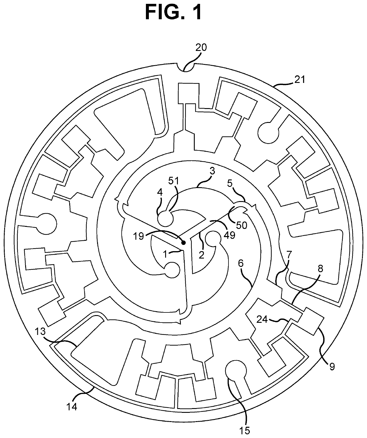
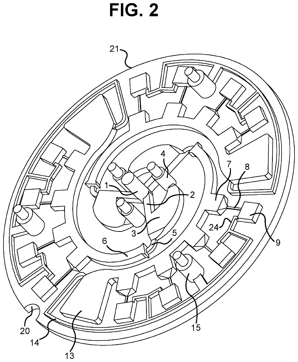
[0051]Embodiments of the invention are intended to partition fluids. To this end, there is a plurality of suitable methods and materials which can be used to produce embodiments of the invention. These materials and methods, along with any surface coatings or device treatments implemented, can be selected to suit a variety of applications, including but not limited to chemical and biological experiments or assays, and medical diagnostics.

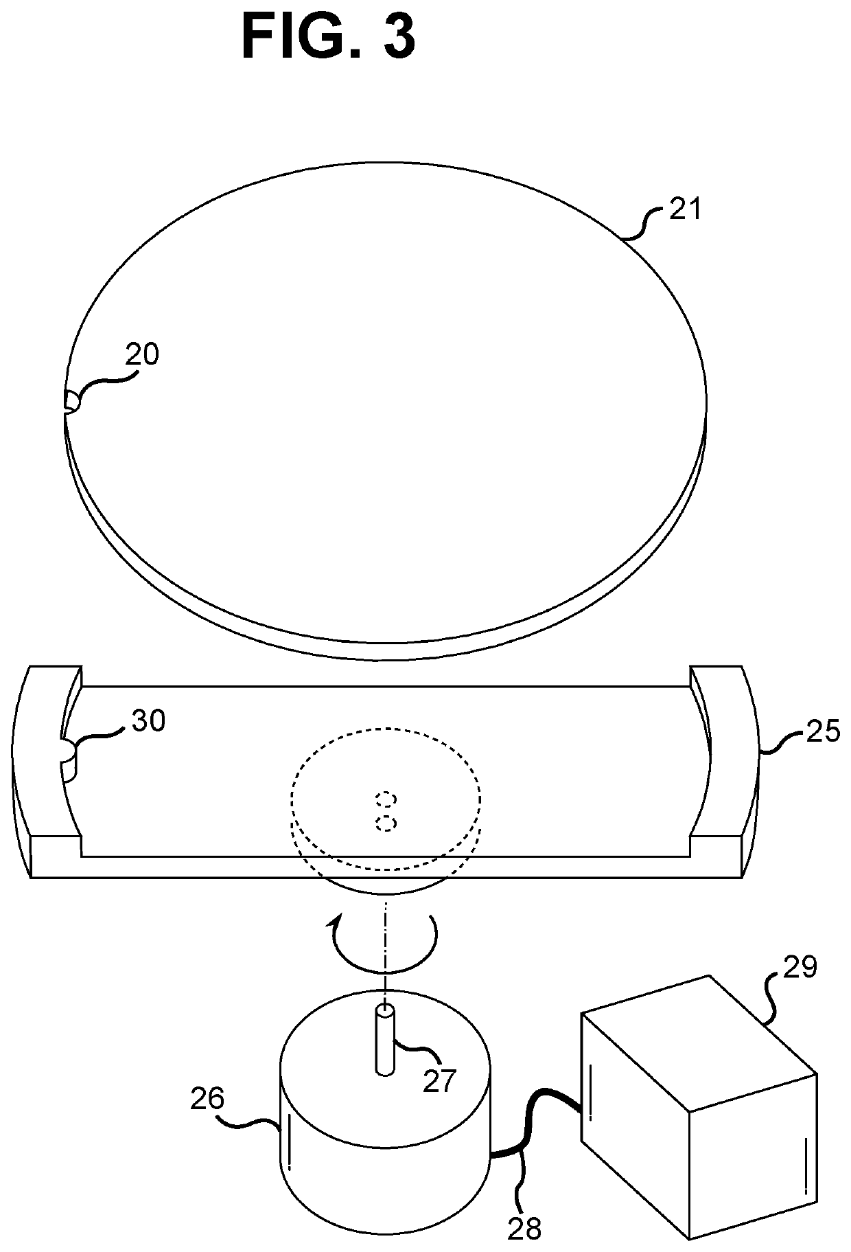
[0052]Embodiments of the invention can be manufactured as two separate halves of a single centrifugal fluidic device bisected by a plane which is coplanar with the plane of rotation of the device. These halves can be joined together, which allows for the loading of reagents or assay materials into the centrifugal fluidic device prior to assembly of the centrifugal fluidic device. These halves do not need to be made from the same material, and can be made from a variety of materials as are suitable to the intended applications of the centrifugal flui...


PUM


Abstract

Embodiments of the invention relate to centrifugal fluidic devices, apparatus, and methods. Embodiments disclosed are fluidic devices, and associated apparatus and methods, which can partition a fluid sample from a single inlet or plurality of inlets into a plurality of chambers via their fluid inlets. Each chamber possesses a fluid outlet and a gas outlet. Partitioned fluid can be further distributed under centrifugal pressure to downstream fluidics modules, permitting various multiplexed assays to be performed including nucleic acid amplification tests.

Description

CROSS-REFERENCE TO RELATED APPLICATIONS[0001]This application claims priority to Hong Kong Patent Application No. 22020006413.1, filed on Apr. 24, 2020, which is incorporated by reference herein in its entirety.TECHNICAL FIELD[0002]Embodiments of the invention relate to centrifugal fluidic devices, apparatus, and methods.BACKGROUND OF THE INVENTION[0003]In various scientific disciplines, especially in the biological and chemical sciences, and in industry and medicine, it is necessary to conduct various assays and experiments in a fluid format. In the biological sciences, for example, these assays can include enzymatic, immunological, metabolic, and / or diagnostic assays. Diagnostic assays in particular are of particular import in medicine, with nucleic acid amplification tests (NAATs) being especially useful. Relying upon polymerase chain reaction (PCR) technology, which is performed in an aqueous format, NAATs are capable of diagnosing not only infectious diseases but also genetic d...

Claims


Application Information

Patent Timeline
IPC IPC(8): B04B5/04B04B11/02
CPCB04B5/0442B04B11/02B01L3/5027B01L3/50273B01L2400/0409B01L2300/0803B01L3/502723B01L2200/0621B01L2300/0864
Inventor SUAREZ, DOMENICK ARRIGO
Owner QUOMMNI TECH LTD
Why Eureka
Try Eureka