Pipe connection arrangement for a heat exchanger

a technology of heat exchanger and connection arrangement, which is applied in the direction of indirect heat exchanger, branching pipes, light and heating apparatus, etc., can solve the problems of further galvanic corrosion between the copper pipe and the aluminium block fitting, the corrosion of the pipe connection is susceptible to galvanic corrosion, and the damage of such corrosion is reduced, so as to reduce the damage of such corrosion and reduce the damage

Pending Publication Date: 2021-10-28
CARRIER CORP
View PDF16 Cites 0 Cited by
  • Summary
  • Abstract
  • Description
  • Claims
  • Application Information

AI Technical Summary

Benefits of technology

[0008]The flange provides a means to secure a pipe to be connected when it is inserted in the bore of the block fitting. The collar of the pipe will be sandwiched between (i.e. located between) the block fitting and the flange, and thus the flange prevents the pipe from slipping out of position. The flange will generally abut the collar when coupled to the block fitting.
[0030]In other examples the surface of the block fitting may be flat or substantially flat; or flat or substantially flat except for the plateau portion; i.e. the spotfacing / recessed area of the prior art may be omitted. Consequently, water retention in the recessed area as occurs in the prior art is avoided. Thus, galvanic corrosion is reduced and the damage resulting from such corrosion is reduced.

Problems solved by technology

However, such pipe connections are susceptible to galvanic corrosion for various reasons.
Firstly, a recessed area in the block fitting (also known as a spotfacing) in which a seal and a collar of the refrigerant pipe are located causes water retention, which leads to galvanic corrosion between the aluminium block fitting, steel flange and copper pipe due in particular to the high potential between the aluminium and copper.
These electrical connections result in further galvanic corrosion between the copper pipe and the aluminium block fitting, and between the steel flange and the aluminium block fitting.
The galvanic corrosion causes damage to the pipe connection arrangement leading to refrigerant leaks.
Moreover, the block fitting becomes unsightly.

Method used


Image

  • Pipe connection arrangement for a heat exchanger
  • Pipe connection arrangement for a heat exchanger
  • Pipe connection arrangement for a heat exchanger

Examples


Embodiment Construction

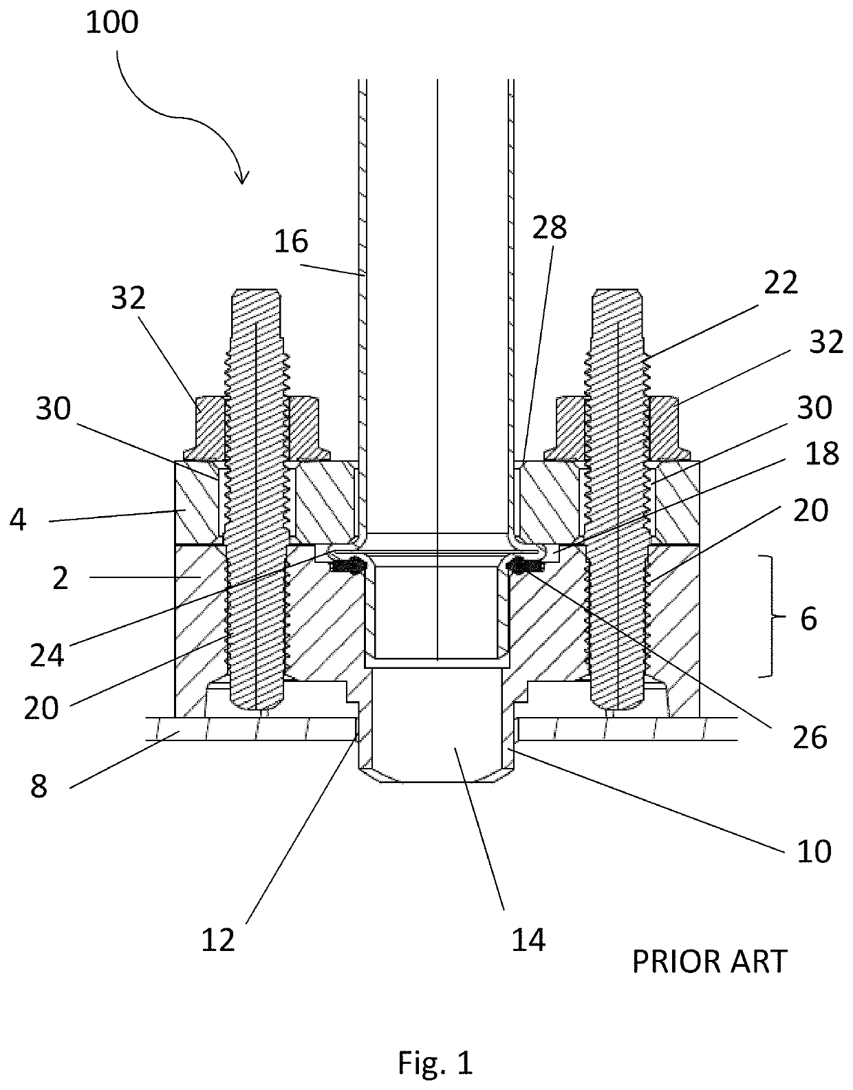
[0066]FIG. 1 shows a conventional pipe connection 100 which may be an inlet and / or an outlet connection for a MCHE. The pipe connection 100 includes a block fitting 2 and a metal flange 4. The block fitting 2 includes a body having a block portion 6 that resides above the exterior surface of a heat exchanger 8 and an insert portion 10 having an outer diameter that is received in the heat exchanger 8. The outer diameter of the insert portion 10 is sized in correspondence with an opening 12 in the heat exchanger 8.

[0067]The block fitting 2 includes a bore 14 which has an opening in and extends from a surface of the block portion 6 that faces the flange 4 when the flange 4 is coupled to the block fitting 2. The bore 14 extends from the surface, through the block fitting 2, to an opening in a lower surface of the insert portion 10. A refrigerant pipe 16 extends partially inside the bore 14. The block fitting 2 thus allows refrigerant to pass through the refrigerant pipe 16 into or out o...


PUM


Abstract

There is provided a pipe connection arrangement for a heat exchanger and a method of connecting a pipe to a heat exchanger utilising a pipe connection arrangement. The pipe connection arrangement includes: a metallic block fitting; a flange for coupling to the block fitting; and a seal. The block fitting includes a bore extending therethrough for receiving a pipe for connection to a heat exchanger and the flange includes a bore extending therethrough for receiving the pipe. The block fitting includes a surface that faces the flange when the flange is coupled to the block fitting. The seal is configured for location between and for abutting both the surface of the block fitting and an annular collar of a pipe when it is connected by the pipe connection arrangement. The pipe extends through the bore of the flange and the flange is coupled to the block fitting.

Description

CROSS-REFERENCE TO RELATED APPLICATIONS[0001]This application claims the benefit of European Application No. 20171435.9 filed Apr. 24, 2020, the disclosure of which is incorporated herein by reference in its entirety.FIELD[0002]The present disclosure relates generally to the field of heat exchangers. In particular, the disclosure relates to a pipe connection arrangement for a heat exchanger, a heat exchanger comprising the pipe connection arrangement and a method of connecting a pipe to a heat exchanger.BACKGROUND[0003]Heat exchangers, in particular Micro Channel Heat Exchangers (MCHE), such as those used in air-cooled chillers, rely on the supply of refrigerant via a refrigerant pipe connected to the heat exchanger. Such a refrigerant pipe is typically made from copper. Conventionally, a refrigerant pipe is connected to a heat exchanger using a block fitting arrangement comprising an aluminium seal washer block heat exchanger fitting (referred to more generally as a block fitting) ...

Claims


Application Information

Patent Timeline
Patent Type & Authority Applications(United States)
IPC IPC(8): F28F9/02
CPCF28F9/0251F28F2275/20F28F9/26F28F11/02F16L23/0283F16L23/18F16L41/086F16L58/188F28B1/06F28D2021/007
Inventor CHANON, JEAN-PIERRENADIN, RENAUDWALLET-LAILY, JEREMYROUSVILLE, BRICE
Owner CARRIER CORP
Why Eureka
Try Eureka