Canister vacuum cleaner with battery-powered floor nozzle

a vacuum cleaner and floor nozzle technology, which is applied in the direction of suction cleaners, suction filters, suction hoses, etc., can solve the problems of low-voltage power to the nozzle from the vacuum cleaner, appreciable heat generation and line losses, and the kind of suction conduit is problematic, so as to prevent any unintentional or malicious loosening of the inner mount and achieve pleasing visual appearance

Active Publication Date: 2021-11-04
WESSEL WERK
View PDF0 Cites 0 Cited by
  • Summary
  • Abstract
  • Description
  • Claims
  • Application Information

AI Technical Summary

Benefits of technology

[0033]In an especially preferred embodiment, the inner mount is fastened on the suction pipe by the outer mount. The inner fastener is concealed and / or secured by the housing held at the inner mount. According to this variant of the invention, the inner fastener is not accessible and is not removable when the housing of the electrical storage device is located in a position held by the inner mount. This prevents the inner mount from coming loose from the suction pipe when the energy storage device is correctly installed.
[0034]The inner fastener may be a latching or screwed connection. In particular, and preferably, it can be on an inside of the inner cap. Provided that the power unit is not accommodated in the cap, an installer can access the fastener from the inside. After the outer fastener is fastened on the suction pipe, the housing of the power unit can then be pushed into the outer cap. This prevents any unintentional or malicious loosening of the inner mount. It also contributes to a pleasing visual appearance if corresponding fastener are not directly visible.

Problems solved by technology

However, this kind of suction conduit is problematic with regard to supplying energy to the electric drive of the cleaning device in the nozzle.
Even low-voltage power to the nozzle from the vacuum cleaner is problematic.
Due to the long line length, appreciable heat generation and line losses can be expected.
Also, cable guides running along a suction hose, for example, always pose the danger of cable breaks due to frequent flexing of the suction hose.
The only way to counteract this is by using extremely costly stranded-copper lines, and this can be uneconomical in the context of a vacuum cleaner.
Because of the disadvantages described, no such design has ever been put on the market.

Method used


Image

  • Canister vacuum cleaner with battery-powered floor nozzle
  • Canister vacuum cleaner with battery-powered floor nozzle
  • Canister vacuum cleaner with battery-powered floor nozzle

Examples


Embodiment Construction

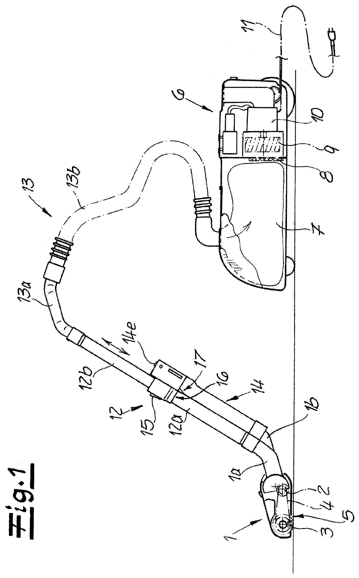
[0049]FIG. 1 shows a vacuum cleaner according to the invention. The vacuum cleaner has a nozzle 1 with an electric motor 2 and a brush roller 3 driven by the electric motor 2 via a toothed belt 4. For purposes of illustrating the nozzle 1 is shown partially in section. The base of the nozzle 1 has a suction intake 5 through which dust-laden air can be drawn into the nozzle 1.

[0050]The vacuum cleaner further has a canister 6 also shown partly in section. The canister 6 contains a dust collector with a filter bag 7 and an open-pored foam filter 8. To generate a suction air stream, a fan 9 powered by an electric drive motor 10 is provided. To drive motor 10 of canister 6 is in turn powered by a line cable 11 that can be retracted into the canister 6.

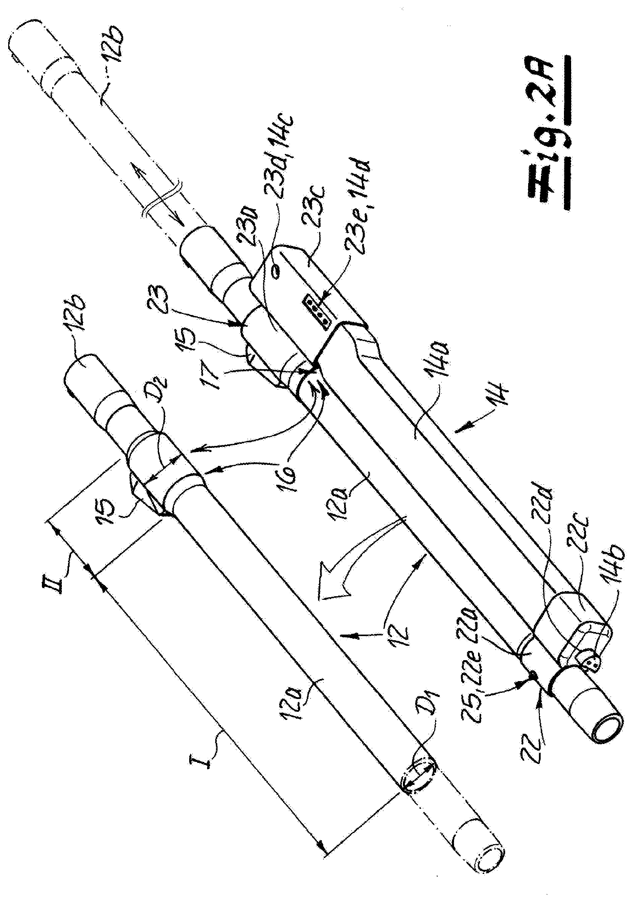
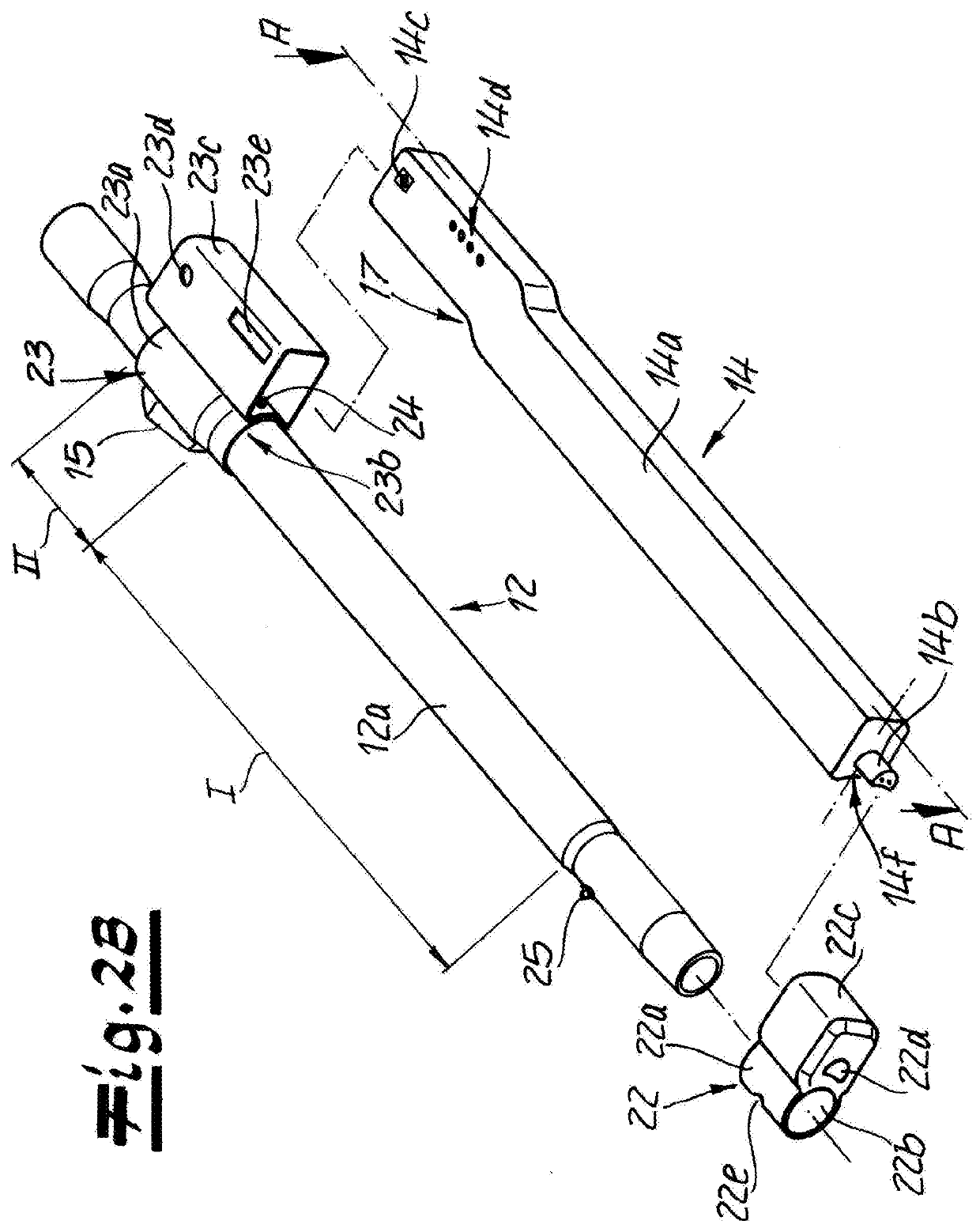
[0051]Air flow from the nozzle 1 to the canister 6 is through a suction conduit 13 that has a rigid, cylindrically tubular suction pipe 12 detachably connected to the nozzle 1 and a suction conduit 13 that connects the inner end of the suct...


PUM


Abstract

A vacuum cleaner has a nozzle with an electric motor and a cleaning device driven thereby. A separate suction unit has an electric fan for drawing in air and a collector for separating dust from the drawn-in air. A suction conduit extends between the nozzle and the suction unit so the electric fan draws air and dust in through the nozzle, pulls it through the conduit, and separates the dust from the air in the collector. The conduit further has a rigid pipe having an outer end connected to the nozzle and an opposite inner end and a flexible hose connected between the inner end and the suction unit and opening into the collector. A power unit for the nozzle motor has a housing mounted on the pipe, a lithium-ion battery contained in the housing, and a control contained in the housing and operating the electric motor of the nozzle from the battery.

Description

FIELD OF THE INVENTION[0001]The present invention relates to a vacuum cleaner. More particularly this invention concerns a canister vacuum cleaner with a powered floor nozzle.BACKGROUND OF THE INVENTION[0002]The invention relates to a vacuum comprising a nozzle, a canister or suction unit and a suction conduit between the nozzle and the canister.[0003]The suction unit has a fan for drawing in air and a collector for separating dirt particles entrained in the suctioned air stream. The collector may preferably be a filter bag, a partially air-permeable filter element such as a filter pad for example, or a foam filter and / or a cyclone filter.[0004]Conventional vacuum cleaners of this type only permit the removal of dirt particles that are loose on a surface to be cleaned, in particular, a floor surface, or that can be easily detached by air movement. To this end, it is also known to provide an electrically powered cleaning device in the nozzle to pick up dust. This can be a driven brus...

Claims


Application Information

Patent Timeline
Patent Type & Authority Applications(United States)
IPC IPC(8): A47L9/28A47L5/36A47L9/04A47L9/24A47L9/10
CPCA47L9/2884A47L5/362A47L9/102A47L9/248A47L9/2847A47L9/0411Y02E60/10
Inventor CLEFF, MARCUS
Owner WESSEL WERK
Why Eureka
Try Eureka