Apparatus and method for detecting grout compactness in grouted splice sleeve

a technology of splice sleeves and apparatus, which is applied in the field of apparatus and methods for detecting grout compactness in splice sleeves, can solve the problems of low mechanization degree, poor working environment, and inability to meet the development needs of the construction industry, and achieve the effect of fast and easy grout compactness detection

Active Publication Date: 2021-11-11
GUANGZHOU MUNICIPAL ENG TESTING CO LTD +2
View PDF9 Cites 10 Cited by
  • Summary
  • Abstract
  • Description
  • Claims
  • Application Information

AI Technical Summary

Benefits of technology

[0080]As compared with the prior art, the present invention is advantageous in that the probe assembly is arranged inside the grouted splice sleeve and forms a loop with the detector during grouting, such that during the process of grouting, the detected parameters will be changed as the surrounding dielectric changes, therefore, the detector may determine in real time whether the grouted splice sleeve is fully grouted by calculating and analyzing the detected parameters, which achieves a faster and easier grout compactness detection.

Problems solved by technology

Conventional cast-in-place construction solutions have fallen short of the development needs for construction industry due to their disadvantages such as inappropriate resource allocation, low mechanization degree, and poor working environment.
However, due to concealment of defects of the grouting in the sleeve, the conventional detecting methods cannot indicate the exact position of defects for reinforcement.
As for nondestructive detecting methods, the methods using ultrasonic wave, impact-echo, or infrared thermal imaging cannot precisely detect and determine the defect position and the defect level of grouting in the sleeve, which realize relative low detection precision; the methods using x-ray CT can obtain high quality images clearly showing internal structure, compactness of the metal sleeve and distribution of the defects in grouting, which realize high precision for grout compactness detection, but the detecting apparatus is huge, complex and is of high cost.
These methods further have disadvantages of radiations and environment pollutions, which are harmful to human beings, and that's why this method has not been widely used.
This method has the advantage of lower cost, but has the disadvantage that the detection cannot be performed until a 3-day curing procedure is finished after the grouting, therefore it cannot achieve real-time detection.
As a result, the grout material may not be replenished in time since the grouting defects are not found during the grouting.
This method cost higher, and the residual grout on the core component of the sensor may be cured and lead to an incorrect detection result, still, this method cannot achieve real-time detection during grouting because the detection cannot be performed until the grouting has been completed.

Method used


Image

  • Apparatus and method for detecting grout compactness in grouted splice sleeve
  • Apparatus and method for detecting grout compactness in grouted splice sleeve
  • Apparatus and method for detecting grout compactness in grouted splice sleeve

Examples


embodiment 1

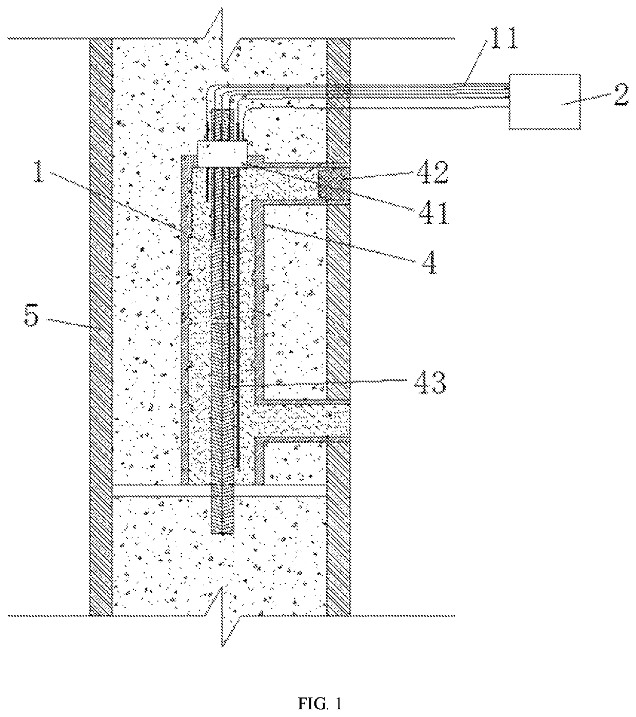
[0116]As shown in FIG. 1, the embodiment provides an apparatus for detecting grout compactness in grouted splice sleeve 4, which comprises a probe assembly 1 arranged inside the grouted splice sleeve 4 for detecting parameters of the grouted splice sleeve 4 during grouting and curing and a detector 2 connected with the probe assembly 1 to obtain the detected parameters and carry out calculations and analysis for the parameters.

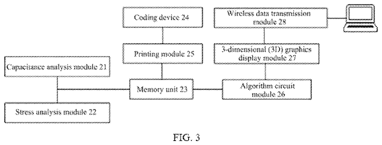
[0117]In this embodiment, the probe assembly 1 comprises at least one capacitive probe Cx to detect capacitance in the grouted splice sleeve 4 during grouting; the detector 2 comprises at least one capacitance analysis module 21 connected to the capacitive probe Cx for calculation and analysis of the capacitance.

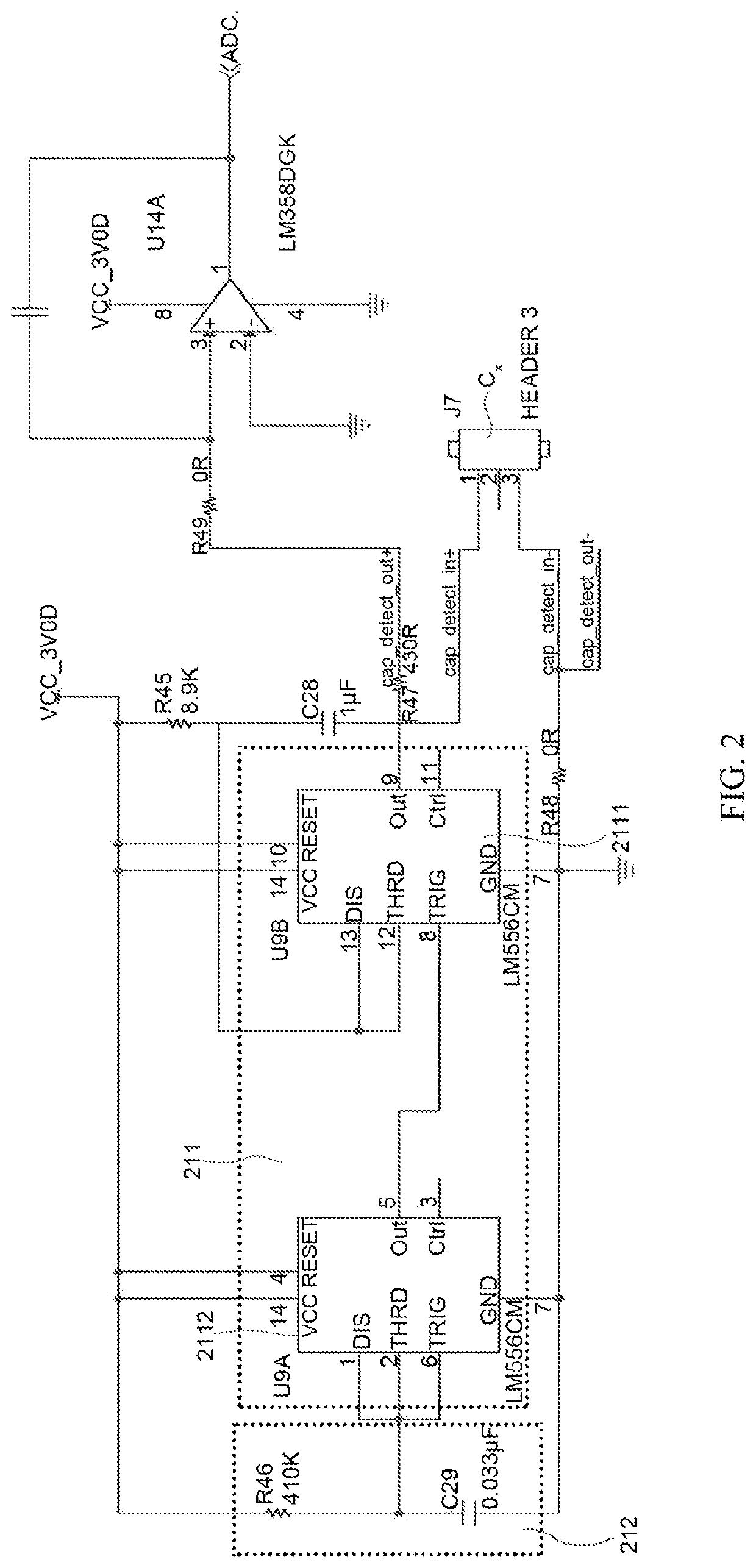
[0118]In this embodiment, the capacitance analysis module 21 comprises a dual time base circuit 211 comprising a first time base circuit 2111 and a second time base circuit 2112 interconnected with each other, a first multi-vibrator 212, and a first sm...

embodiment 2

[0126]This embodiment provides another apparatus for detecting grout compactness in grouted splice sleeve 4, which comprises a probe assembly 1 arranged inside the grouted splice sleeve 4 for detecting parameters of the grouted splice sleeve 4 during grouting and curing and a detector 2 connected with the probe assembly 1 to obtain the detected parameters and carry out calculation and analysis for the parameters. The probe assembly 1 comprises at least one piezoelectric sensor r for detecting stress level in the grouted splice sleeve 4 during grouting; the detector 2 comprises at least one stress analysis module 22 connected to the piezoelectric sensor for calculation and analysis of stress value.

[0127]As shown in FIG. 7, the stress analysis module 22 comprises a time base circuit 221 connected to the piezoelectric sensor r for obtaining resonance frequency signal; a second multi-vibrator 222 connected to the time base circuit 221 for outputting a voltage signal according to the res...

embodiment 3

[0134]A method for detecting grout compactness in grouted splice sleeve 4 is further provided in this embodiment. As shown in FIG. 8, the method comprises the following steps,

[0135]S1. Inserting the probe assembly 1 into the grouted splice sleeves 4;

[0136]S2. Providing a predetermined threshold range on the detector 2;

[0137]S3. Obtaining the parameters of the grouted splice sleeves 4 by the detector 2 throughout the grouting process;

[0138]S4. Comparing the detected parameter with the threshold range, the grouted splice sleeves 4 will be determined as fully grouted if the detected parameter is within the threshold range, whereas the grouted splice sleeves 4 will be determined as defectively grouted if the detected parameter is out of the threshold range.

[0139]The probe assembly 1 in this embodiment comprises at least a capacitive probe, the parameter to be detected is a capacitance, and the threshold range is a threshold range of the capacitance value; the detector 2 comprises at lea...


PUM

PropertyMeasurementUnit
capacitanceaaaaaaaaaa
diameteraaaaaaaaaa
capacitanceaaaaaaaaaa

Abstract

Provided is an apparatus and method for detecting grout compactness in grouted splice sleeve, the apparatus comprises a probe assembly, which comprises at least one of capacitive probe and piezoelectric sensor and is arranged inside the grouted splice sleeve to detect parameters of the sleeve during grouting and curing and a detector, which comprises at least an analysis module that is connected with the probe assembly to obtain the detected parameters and carry out calculation and analysis for the parameters. The probe assembly is arranged inside the grouted splice sleeve and forms a loop with the detector during grouting, such that during the process of grouting, the detected parameters will be changed as the surrounding dielectric changes, therefore, the detector may determine in real time whether the grouted splice sleeve is fully grouted by calculating and analyzing the detected parameters, which achieves a faster and easier grout compactness detection.

Description

CROSS REFERENCE TO RELATED APPLICATION[0001]This application claims priorities of Application nos. 202010387644.6 and 202010388646.7 both filed in China on May 9, 2020, under U.S.C. § 119, the entire contents of which are hereby incorporated by reference.TECHNICAL FIELD[0002]The following relates to the field of construction quality detection, in particular to apparatus and method for detecting grout compactness in grouted splice sleeve.BACKGROUND OF INVENTION[0003]With the rapid development of domestic economy and urbanization, the building industrialization is also expedited. Conventional cast-in-place construction solutions have fallen short of the development needs for construction industry due to their disadvantages such as inappropriate resource allocation, low mechanization degree, and poor working environment. In recent years, prefabricated construction, which is a standardized and green architectural form having the advantages of rapid construction, energy saving, environme...

Claims


Application Information

Patent Timeline
Patent Type & Authority Applications(United States)
IPC IPC(8): G01N33/38
CPCG01N33/383
Inventor TANG, MENGXIONGZHOU, ZHIGUOSUN, XIAOLIWANG, HONGYEYANG, JUNHU, HESONGZHOU, WUYANGBIAN, DECUNZHAO, YAYUSHAO, JIXIGUO, DUCHENGZHAO, HONGBIN
Owner GUANGZHOU MUNICIPAL ENG TESTING CO LTD
Why Eureka
Try Eureka