
Systems and methods for selective molecular ion deposition

a selective molecular ion and molecular ion technology, applied in the field of ion manipulation, can solve the problems of low ion utilization efficiency and sample loss, inefficient ion utilization, and limited resolution achieved by dtims

Pending Publication Date: 2021-11-11
BATTELLE MEMORIAL INST
View PDF0 Cites 0 Cited by
  • Summary
  • Abstract
  • Description
  • Claims
  • Application Information

AI Technical Summary

Benefits of technology

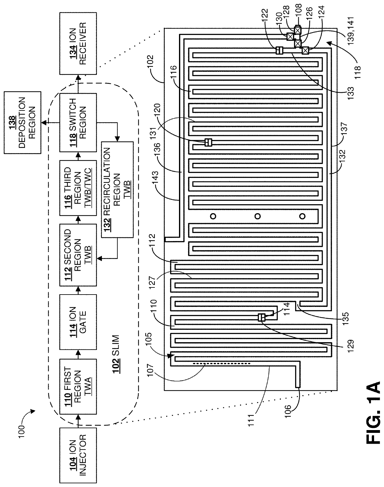
The patent describes a method and apparatus for separating and depositing ions based on their mobility and arrival time on a substrate. The method involves directing ions through an ion manipulation apparatus and selecting a subset of ions based on their ion arrival time on the substrate. The selected ions can be directed to specific locations on the substrate or printed in three-dimensional structures using a 3D ion printer. The apparatus includes an ion separation region, an ion switch region, and an ion deposition region. The method can also involve confirming the selection of the selected ions through a mass spectrometer. The patent also describes a multi-ion separator system that includes multiple ion separation apparatus and an ion deposition system.

Problems solved by technology

In relatively long path length separations, notably using SLIMs, separation times combined with traditional ion injection techniques can lead to low ion utilization efficiency and loss of sample.
Despite having the ability to accumulate ions for relatively longer times using on-board ion accumulation in SLIM, the long separations that subsequently follow can lead to inefficient ion utilization.
The resolution achieved by DTIMS, however, is restricted due to limitations in the maximum voltage drop across the drift tube and / or the length of the drift tube itself.
However, IMS-MS instruments are not utilized for selective material surface preparation because chemical analysis results in destruction of the sample at the analytical device.
While there have been attempts to improve the ion utilization efficiency of SLIM, these approaches are still limited to utilization of 50% or below.
As a result, ion utilization and throughput remain a significant challenge, and efficient deposition of selected molecules is prevented.
For example, higher voltages during accumulation can produce voltage-induced fragmentation and / or physical losses by escaping confinement barriers.
However, relatively longer injection times tE cause an undesired increase in analysis times, which ultimately limits ion utilization efficiency.
As mentioned, a significant difference between the concurrent method of the SLIM 902 and B-N gate injection, among other things, is that B-N gate injection does not allow for extended ion accumulation.
Isomers of a given ion species, for example, can have the same mass but different ion mobilities due to variations in the isomer structures, variations which can be difficult to distinguish based on mass alone.

Method used


Image

  • Systems and methods for selective molecular ion deposition
  • Systems and methods for selective molecular ion deposition
  • Systems and methods for selective molecular ion deposition

Examples


— example 1

Concurrent Separation and Accumulation—Example 1

[0094]FIGS. 6A-6F are a time series of diagrams illustrative of a representative method 600 for concurrent ion separation and accumulation using a SLIM 602 of the disclosed technology. FIG. 6A shows the SLIM 602 at a time t0 immediately before injection of an accumulated ion set 604 and the beginning of a separation window. At time to, the ion set 604 is confined within a confinement volume of an accumulation region 606 of the SLIM 602 between an ion entrance 614 and an ion gate 608. The ion set 604 can include ions from one or more ion pulses received from an ion gate 610, such as a Bradbury-Nielson grid gate, situated upstream from the ion entrance 614. The ion gate 610 at time t0 is in a closed state such that the flow of ions into the SLIM 602 is stopped.

[0095]The ion gate 608 is situated at an interface between the accumulation region 606 and a separation region 612. The ion gate 608 is configured to produce a DC voltage to confin...

— example 2

Concurrent Separation and Accumulation—Example 2

[0104]FIG. 7 is a method 700 of concurrently separating and accumulating ions using a SLIM. At 702, the method 700 includes separating a first set of ions in a separation region of an ion manipulation apparatus while accumulating a second set of ions in an accumulation region of the ion manipulation apparatus. The first set of ions being separated within the separation region at 702, can be ions earlier received from the accumulation region through an ion gate of the ion manipulation device. The ion gate is situated at an interface of the separation region and the accumulation region where the two regions are coupled and configured to inject ions from the accumulation region to the separation region.

[0105]At 704, one or more ion packets of the first set of ions having traveled at least partially through the separation region can be selected for recirculation and reintroduced back into the separation region for further separation. Any o...

— example 3

Concurrent Separation and Accumulation—Example 3

[0107]FIG. 8 is a method 800 for concurrent ion separation and accumulation using a SLIM of the disclosed technology. The method 800 is similar to the method 700, but further includes ion peak compression. For instance, at 802, the method 800 includes separating a first set of ions in a separation region of an ion manipulation apparatus while accumulating a second set of ions in an accumulation region of the ion manipulation apparatus. An ion gate situated at an interface of the separation region and the accumulation region is configured to inject ions from the accumulation region into the separation region.

[0108]At 804, the method 800 includes compressing at least a portion of the first set of ions in a compression region of the ion manipulation apparatus while accumulating the second set of ions in the accumulation region. The compression region is coupled to the separation region at one end and a switch region of the ion manipulatio...


PUM


Abstract

Methods include directing a group of ions through a separation region of an ion manipulation apparatus, separating the group of ions in the separation region based on ion mobility, selecting a subset of the group of ions based on a dependence between ion mobility and ion arrival time of the separated ions at a deposition switch of the ion manipulation apparatus, and depositing the selected subset of ions on a substrate. Related systems and ion manipulation apparatus are disclosed. Also disclosed are methods and system that provide concurrent ion accumulation and ion separation in coupled and switchable electrode regions using traveling wave electric fields.

Description

CROSS REFERENCE TO RELATED APPLICATION[0001]This application claims the benefit of U.S. Provisional Application No. 63 / 021,582, filed May 7, 2020. The prior application is incorporated herein by reference in its entirety.ACKNOWLEDGMENT OF GOVERNMENT SUPPORT[0002]This invention was made with Government Support under Contract DE-AC05-76RL01830 awarded by the U.S. Department of Energy. The Government has certain rights in the invention.FIELD[0003]The present disclosure relates to ion manipulation.BACKGROUND[0004]The ability to separate ions using ion mobility and mass spectrometry provides separation based on molecular mass and size. Previous approaches to mass selective ion deposition are typically limited to a selected mass of the ions. Further, previous approaches deposit small amounts of material over extensive timeframes, making deposition impractical. Accordingly, a need remains for new approaches to selective ion deposition.SUMMARY[0005]According to one aspect of the disclosed t...

Claims


Application Information

Patent Timeline
IPC IPC(8): H01J37/317H01J27/02H01J37/30
CPCH01J37/3178B33Y30/00H01J37/3007H01J27/022B33Y10/00G01N27/623H01J49/062G01N27/622
Inventor GARIMELLA, SANDILYA V.B.IBRAHIM, YEHIA M.LI, AILINSMITH, RICHARD D.
Owner BATTELLE MEMORIAL INST
Features
  • Generate Ideas
  • Intellectual Property
  • Life Sciences
  • Materials
  • Tech Scout
  • Unparalleled Data Quality
  • Higher Quality Content
  • 60% Fewer Hallucinations
Learn More