Decontamination Device for Inhaled and Exhaled Ventilator Gases

a ventilator gas and decontamination device technology, which is applied in the direction of respirators, lighting and heating apparatus, heating types, etc., can solve the problems of hammering the patient's ability to breathe and exchange oxygen and carbon dioxide, ineffective filters, and serious environmental contamination risks, so as to reduce the flow of ventilators and increase resistance.

Pending Publication Date: 2021-11-25
HABASHI NADER M
View PDF0 Cites 1 Cited by
  • Summary
  • Abstract
  • Description
  • Claims
  • Application Information

AI Technical Summary

Benefits of technology

[0009]It is an object of the invention to provide a decontamination device that does not interfere with patient's breathing by reducing ventilator flow which increases resistance.

Problems solved by technology

Such infectious diseases affect respiratory system, including lungs of a patient and thus hampers the patient's ability to breathe and exchange oxygen and carbon dioxide.
In situations where a turbine may be used to entrain environmental air and gas, and the environment may be contaminated, inspired gas may entrain pathogens or chemicals into the ventilator.
Thus, even with these filters, there is a serious risk of environmental contamination.
The filters are not efficient in filtering out the contaminants in the inhaled or exhaled gases, and thus enter the patient's lungs and the patient's ambient environment, which subjects the patient and those exposed to the environment around the patient to a risk of respiratory infections from contaminants.
This risk is due not only to the difficulty in filtering contaminants in the inhaled or exhaled gases, but also to the high clinical prevalence of respiratory infection causing contaminants.
For example, during SARS, the ICU room contamination was high despite the use of expiratory filters.
Contaminated condensates can potentially pass through some filters under typical pressures encountered during mechanical ventilation.
In addition, masks are used, but the masks are prone to leakages.
Further, the efficacy of expiratory filters is unknown in testing and raises the concern for risks of environmental contamination such as in the intensive care unit (ICU), operating room (OR) or during inter or intra-hospital transport.
However, UV light used to decontaminate the contaminants in the inhaled or exhaled air are currently not efficient.

Method used


Image

  • Decontamination Device for Inhaled and Exhaled Ventilator Gases
  • Decontamination Device for Inhaled and Exhaled Ventilator Gases
  • Decontamination Device for Inhaled and Exhaled Ventilator Gases

Examples


Embodiment Construction

lass="d_n">[0037]Reference will now be made in detail to specific embodiments or features, examples of which are illustrated in the accompanying drawings. Wherever possible, corresponding, or similar reference numbers will be used throughout the drawings to refer to the same or corresponding parts. Moreover, references to various elements described herein, are made collectively or individually when there may be more than one element of the same type. However, such references are merely exemplary in nature. It may be noted that any reference to elements in the singular may also be construed to relate to the plural and vice-versa without limiting the scope of the disclosure to the exact number or type of such elements unless set forth explicitly in the appended claims.

[0038]In the interest of clarity, not all of the routine features of the implementations described herein are shown and described. It will, of course, be understood that in the development of any such actual implementati...


PUM

PropertyMeasurementUnit
distanceaaaaaaaaaa
distanceaaaaaaaaaa
wavelengthaaaaaaaaaa

Abstract

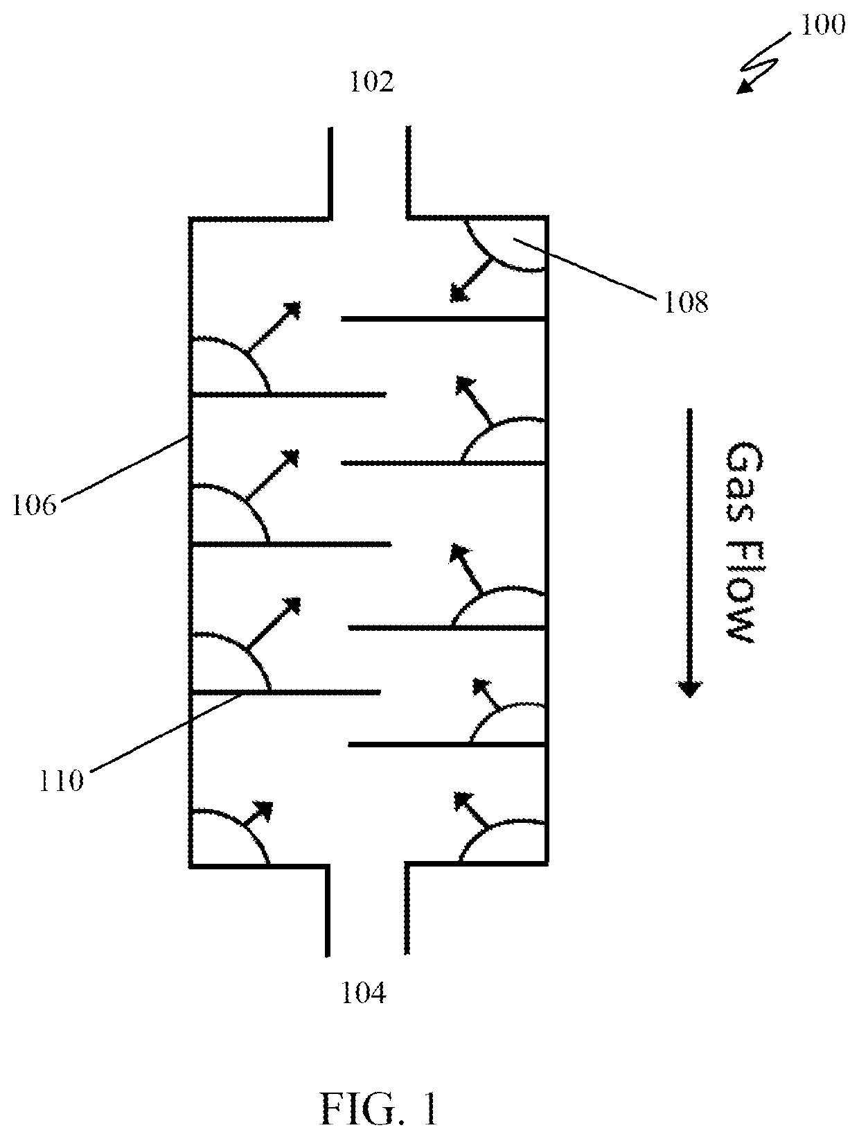
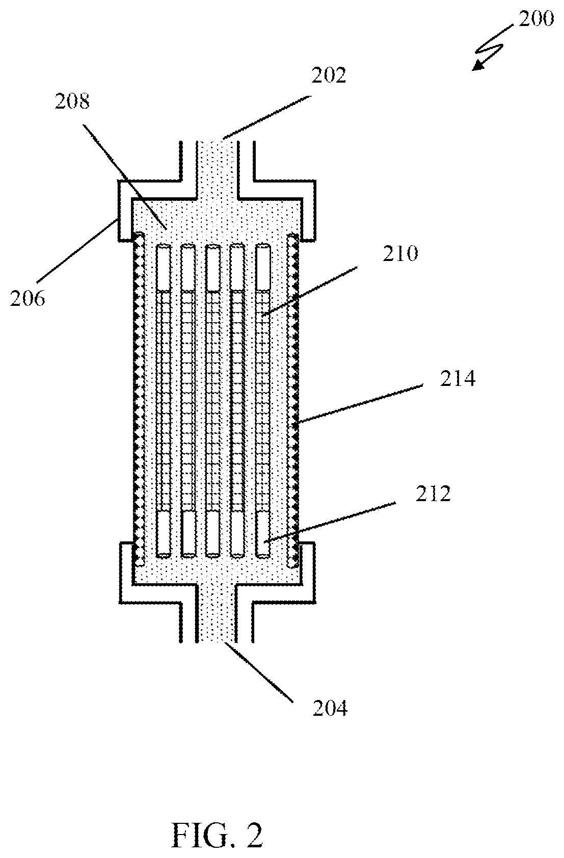
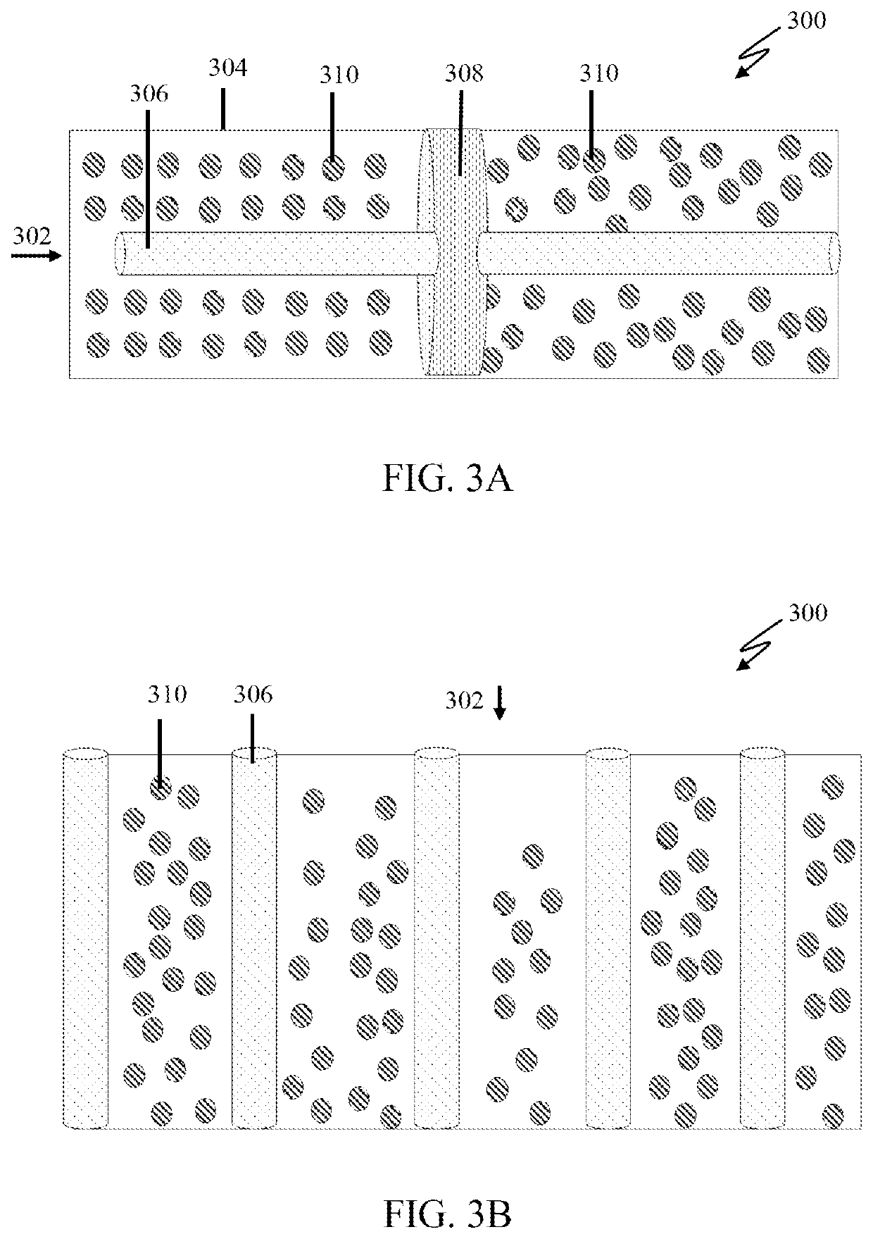
The invention discloses a decontamination device for decontaminating inhaled and/or exhaled gases in a ventilator. The decontamination device comprises a gas inlet and outlet for inspiratory and expiratory gas flow, and a chamber for gas flow. The chamber is configured to connect the gas inlet and outlet. The chamber comprises at least one ultraviolet (UV) light source integrate inside the chamber that preferably emits in the UVC range, wherein the UV light source is preferably a UVC light-emitting diode. The UV light source is configured to produce UV light to decontaminate contaminants in the inhaled and/or exhaled gases by minimizing the distance between the contaminants in the gas flow and the light source, maintaining the gas flow in a gas flow path long enough to deactivate the contaminants, increasing the intensity of the light source to optimize decontamination, and increasing turbulence to redirect the gas flow and prevent boundary layers and shadowing.

Description

CROSS-REFERENCE TO RELATED APPLICATIONS AND CLAIM TO PRIORITY[0001]This application relates to Provisional Application Ser. No. 63 / 027,342 filed May 19, 2020, the disclosure of which is incorporated herein by reference and to which priority is claimed.FIELD OF THE DISCLOSURE[0002]The invention generally relates to a decontamination device as well as a ventilator comprising a decontamination device. More specifically, the invention relates to a device that uses ultraviolet (UV) light to decontaminate inhaled and / or exhaled gases from a ventilator and a ventilator comprising such a device.BACKGROUND OF THE DISCLOSURE[0003]Currently, infectious diseases such as influenza, SARS, COVID-19, coronavirus, bacteria, and other viruses, cause mortality and morbidity via respiratory infection. Such infectious diseases affect respiratory system, including lungs of a patient and thus hampers the patient's ability to breathe and exchange oxygen and carbon dioxide. With the advancement in technolog...

Claims


Application Information

Patent Timeline
Patent Type & Authority Applications(United States)
IPC IPC(8): A61M16/00A61L9/20
CPCA61M16/009A61M2206/16A61L9/20F24F8/22A61M16/107A61M16/0087A61M2205/053A61M2209/10A61M2206/14A61M16/0003A61M2202/20A61M2202/203A61M2202/206A61M16/10A61M16/1065A61M16/1055A61M16/125A61M2202/0208A61M16/0066
Inventor HABASHI, NADER M.
Owner HABASHI NADER M
Why Eureka
Try Eureka