Eureka AIR delivers breakthrough ideas for toughest innovation challenges, trusted by R&D personnel around the world.

Refrigeration cycle apparatus

Pending Publication Date: 2021-12-02
MITSUBISHI ELECTRIC CORP
View PDF0 Cites 0 Cited by
  • Summary
  • Abstract
  • Description
  • Claims
  • Application Information

AI Technical Summary

Benefits of technology

The refrigeration cycle apparatus described in this patent reduces the heat-exchange capability of the evaporator during low load operations, without changing the rotation speed of the compressor. This allows for a reduction in the refrigeration cycle apparatus' capacity without increasing the compressor's workload. Additionally, the apparatus reduces the repetition of stopping and starting of the compressor.

Problems solved by technology

Therefore, if the rotation speed of the compressor is excessively reduced, refrigerating machine oil cannot be sufficiently supplied the slide portion, and as a result, the reliability of the compressor is reduced.
Therefore, when the refrigeration cycle apparatus performs the intermittent operation, the operation efficiency of the refrigeration cycle apparatus is reduced.
Consequently, the operation efficiency of the air-conditioning apparatus is greatly reduced.

Method used


Image

  • Refrigeration cycle apparatus
  • Refrigeration cycle apparatus
  • Refrigeration cycle apparatus

Examples


embodiment 1

[Configuration of Refrigeration Cycle Apparatus 200]

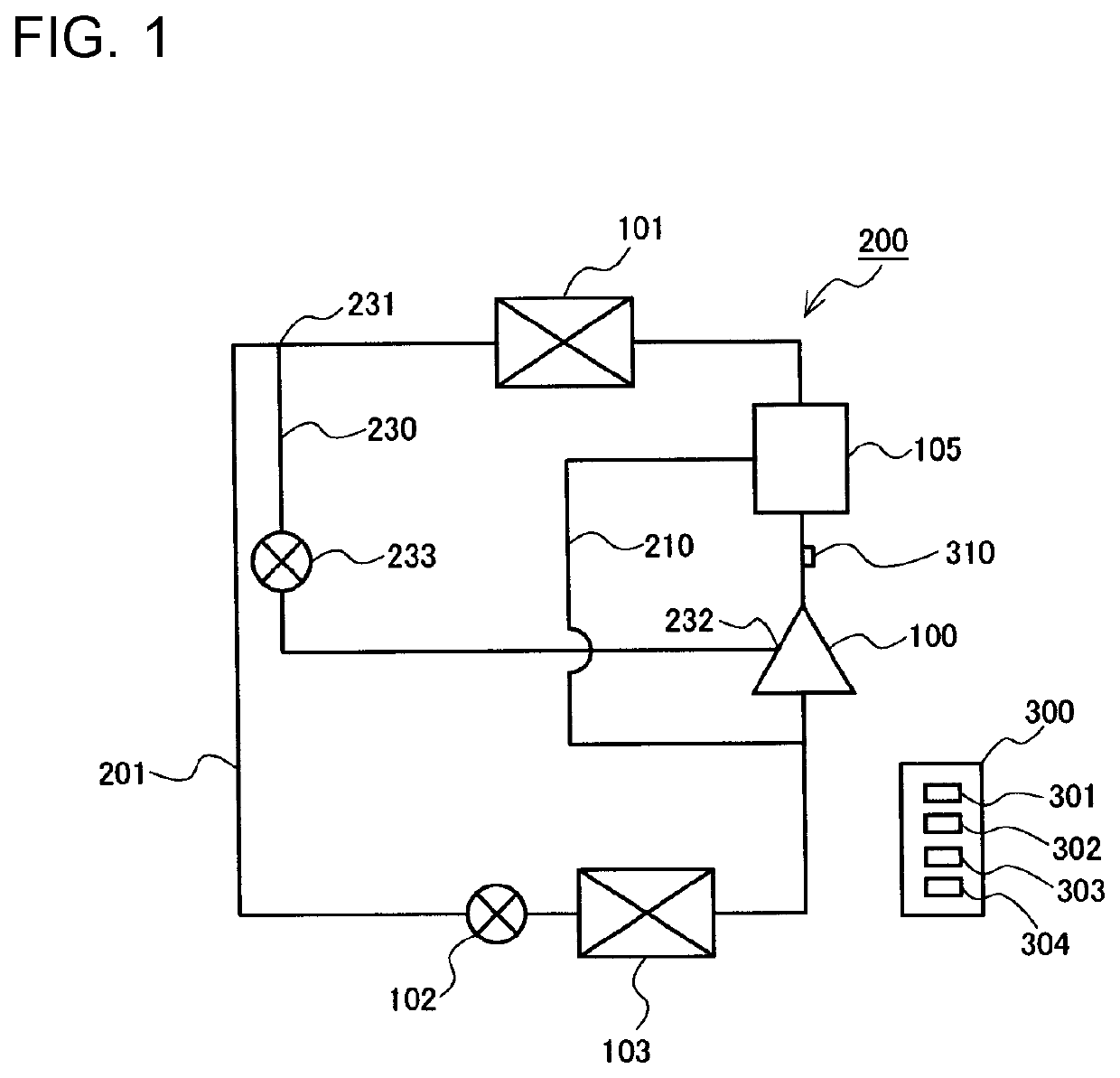
[0023]FIG. 1 is a refrigerant circuit diagram of a refrigeration cycle apparatus according to Embodiment 1 of the present disclosure.

[0024]The refrigeration cycle apparatus 200 includes a refrigeration cycle circuit 201 in which a compressor 100, a condenser 101, a first expansion valve 102, and an evaporator 103 are connected by refrigerant pipes.

[0025]The compressor 100 sucks low-pressure gas refrigerant, compresses the low-pressure gas refrigerant into high-temperature and high-pressure gas refrigerant, and discharges the high-temperature and high-pressure gas refrigerant. The condenser 101 has a refrigerant inflow portion that is connected to a discharge portion of the compressor 100 by a refrigerant pipe, and a refrigerant outflow portion that is connected to a refrigerant inflow portion of the first expansion valve 102 by a refrigerant pipe. The condenser 101 condenses, into high-pressure liquid refrigerant, the high-temperat...

embodiment 2

[0089]FIG. 6 is a refrigerant circuit diagram of a refrigeration cycle apparatus according to Embodiment 2 of the present disclosure. Regarding Embodiment 2, matters that will not particularly be described are similar to those of Embodiment 1, and functions and components that are similar to those of Embodiment 1 will be described with reference to the same reference signs.

[0090]The refrigeration cycle apparatus 200 according to Embodiment 2 includes an oil branch pipe 211 in addition to the components of the refrigeration cycle apparatus 200 according to Embodiment 1. One end of the oil branch pipe 211 is connected to the oil return pipe 210. The other end of the oil branch pipe 211 is connected to part of the injection pipe 230 that is located downstream of the second expansion valve 233. The refrigeration cycle apparatus 200 according to Embodiment 2 is configured such that during the low load operation, refrigerating machine oil that has passed through the oil return pipe 210 an...

embodiment 3

[0095]As described below, a bypass pipe 240, a third expansion valve 241, and a heat exchanger 242 may be added to the refrigeration cycle apparatus 200 according to Embodiment 1 or 2. As described above, also, in the normal operation, refrigerant may be supplied from the injection pipe 230 to the compressor 100. Because of the addition of the bypass pipe 240, the third expansion valve 241, and the heat exchanger 242, it is possible to reduce deterioration of the capacity of the refrigeration cycle apparatus 200 that occurs in the case of supplying refrigerant from the injection pipe 230 to the compressor 100 during the normal operation. It should be noted that regarding Embodiment 3, mattes that will not particularly be described are similar to those of Embodiment 1 or 2, and functions and components that are similar to those of Embodiment 1 or 2 will be described with reference to the same reference signs. The following description is made by referring to by way of example the cas...


PUM


Abstract

A refrigeration cycle apparatus includes: a refrigeration cycle circuit in which a compressor, a condenser, a first expansion valve, and an evaporator are connected by refrigerant pipes; an injection pipe having a refrigerant inflow side end and a refrigerant outflow side end, the refrigerant inflow side being connected between the condenser and the first expansion valve, the refrigerant outflow side end being connected to a suction side of the compressor; a second expansion valve provided at the injection pipe; and a controller that controls a rotation speed of the compressor and an opening degree of the second expansion valve. In the case of reducing a heat-exchange capability of the evaporator when the rotation speed of the compressor is a specified rotation speed, the controller performs a low load operation during which refrigeration is caused to flow through the injection pipe.

Description

TECHNICAL FIELD[0001]The present disclosure relates to a refrigeration cycle apparatus that reduces repetition of stopping and starting of a compressor during an operation at a low load.BACKGROUND ART[0002]The capacity of a refrigeration cycle apparatus is adjusted by changing the rotation speed of a compressor based on a thermal load that is processed by the refrigeration cycle apparatus. Therefore, as the thermal load to be processed decreases, the rotation speed of the compressor is reduced. It should be noted that that refrigerating machine oil is supplied to a slide portion of the compressor, using rotation of a driving shaft of the compressor. Therefore, if the rotation speed of the compressor is excessively reduced, refrigerating machine oil cannot be sufficiently supplied the slide portion, and as a result, the reliability of the compressor is reduced. Thus, in the compressor, a lower limit rotation speed is specified in order to ensure reliability of the compressor.[0003]Wh...

Claims


Application Information

Patent Timeline
IPC IPC(8): F25B49/02F25B41/20F25B41/31F25B1/04
CPCF25B49/027F25B41/20F25B41/31F25B49/022F25B1/04F25B2400/13F25B2600/025F25B2700/21163F25B2500/16F25B2600/2513F25B2600/2509F25B2400/0409F25B1/00F25B40/02F25B2600/2519F04C18/0215F25B31/004F25B2600/2501F25B41/385F25B41/00F25B2700/21152F04C29/0014F04C23/008F04C2240/806F04C28/08F25B2700/171F25B2600/0253F25B41/42
Inventor IMANISHI, TOSHIKITATSUWAKI, KOHEI
Owner MITSUBISHI ELECTRIC CORP
Why Eureka
Eureka Blog
Learn More