
Vision inspection system and method of inspecting parts

a technology of inspection system and inspection method, applied in the field of vision inspection system, can solve the problems of low detection accuracy, poor product consistency, laborious and high cost of manual inspection system, etc., and achieve the effect of improving image contrast, enhancing images, and improving image contras

Pending Publication Date: 2021-12-09
TYCO ELECTRONICS (SHANGHAI) CO LTD +1
View PDF13 Cites 1 Cited by
  • Summary
  • Abstract
  • Description
  • Claims
  • Application Information

AI Technical Summary

Benefits of technology

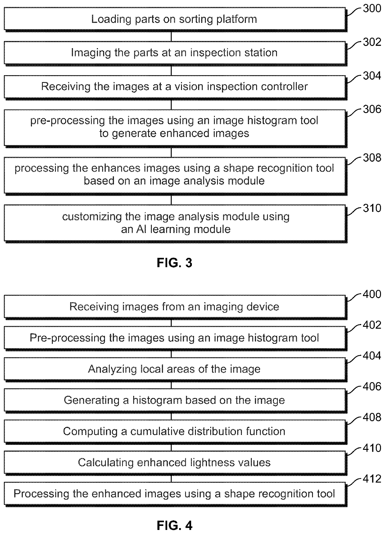
The vision inspection system described in this patent helps to detect and identify parts that may have defects or be misplaced during an inspection process. The system uses an image analysis model that is trained and customized based on images captured by an imaging device. The system can improve the contrast of the images by adjusting the brightness values and detecting specific features within the images. Additionally, the system can identify different parts and their shapes, and even determine if parts are properly positioned on a sorting platform. The goal is to improve the accuracy and efficiency of inspection processes by automating the detection of defective or misplaced parts.

Problems solved by technology

Such manual inspection systems are labor intensive and high cost.
The manual inspection systems have low detection accuracy leading to poor product consistency.
Additionally, manual inspection systems suffer from human error due to fatigue, such as missed defects, wrong counts, misplacing of parts, and the like.
Image quality is a problem with known machine vision inspection systems.
For example, poor image quality due to poor image contrast, poor image brightness, and the like result in poor system performance and faulty inspection.
However, imaging the parts multiple times results in slow throughput.

Method used


Image

  • Vision inspection system and method of inspecting parts
  • Vision inspection system and method of inspecting parts
  • Vision inspection system and method of inspecting parts

Examples


Embodiment Construction

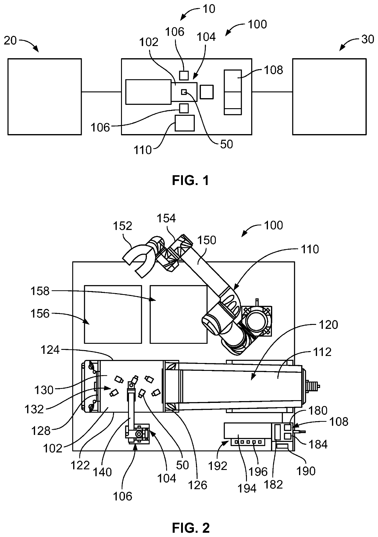
[0016]FIG. 1 is a schematic illustration of a machine 10 for manufacturing parts 50, such as parts used in electrical connectors. For example, the parts 50 may be contacts, housings, circuit boards, or other types of parts. The machine 10 may be used for manufacturing parts used in other industries. The machine 10 includes one or more forming machines 20 used to form various parts 50. For example, the forming machines 20 may include a molding machine, a press, a lathe, and the like. The machine 10 includes a vision inspection system 100 used to inspect the various parts 50. The machine 10 includes one or more processing machines 30 used for processing the various parts 50. For example, the processing machines 30 may include assembly machines, packaging machines, and the like. For example, in various embodiments, the parts 50 may be assembled, such as at an assembly station, prior to packaging, such as at a packing station. The parts 50 are transported between the forming machines 20...


PUM

PropertyMeasurementUnit
brightnessaaaaaaaaaa
field of viewaaaaaaaaaa
shapesaaaaaaaaaa

Abstract

A vision inspection system includes a sorting platform having an upper surface supporting parts for inspection. An inspection station is positioned adjacent the sorting platform including an imaging device to image the parts in a field of view. A vision inspection controller receives images from the imaging device. The vision inspection controller includes an image histogram tool to pre-process the images to improve contrast of the images by redistributing lightness values of the images based on adaptive histogram equalization processing to generate enhanced images. The vision inspection controller processes the enhanced images based on an image analysis model to determine inspection results for each of the parts. The vision inspection controller has an artificial intelligence learning module operated to customize and configure the image analysis model based on the enhanced images.

Description

CROSS REFERENCE TO RELATED APPLICATIONS[0001]This application claims benefit to Chinese Application No. 202010493394.4, filed 3 Jun. 2020, the subject matter of which is herein incorporated by reference in its entirety.BACKGROUND OF THE INVENTION[0002]The subject matter herein relates generally to vision inspection systems.[0003]Inspection systems are used for inspecting parts during a manufacturing process. Conventional inspection systems use personnel to manually inspect parts, such as to identify defective parts. Such manual inspection systems are labor intensive and high cost. The manual inspection systems have low detection accuracy leading to poor product consistency. Additionally, manual inspection systems suffer from human error due to fatigue, such as missed defects, wrong counts, misplacing of parts, and the like. Some known inspection systems use machine vision for inspecting parts. The machine vision inspection systems use cameras to image the parts. Image quality is a p...

Claims


Application Information

Patent Timeline
Patent Type & Authority Applications(United States)
IPC IPC(8): B07C5/342G01N21/88B07C5/36G06T5/40G06T5/00G06T7/00G06K9/62
CPCB07C5/3422G01N21/8851B07C5/362G06T5/40G06T5/009G06K2209/19G06K9/6217G01N2021/8887G06T2207/20081G06K2209/01G06T7/0004B07C5/00B07C5/38B07C5/02B07C2501/0063G06T2207/20012G06T2207/20016G06T7/001B07C5/342G06V2201/06G06V30/10G06V10/255G01N21/956G01N2021/8883G06T5/90G06T2200/28G06F18/21G06T5/92
Inventor LU, ROBERTO FRANCISCO-YIOSUNKWO, SONNY O.ZHANG, DANDANZHOU, JIANKUNZHOU, LEI
Owner TYCO ELECTRONICS (SHANGHAI) CO LTD
Learn More