
Fan assembly

Pending Publication Date: 2021-12-09
DYSON TECH LTD
View PDF19 Cites 1 Cited by
  • Summary
  • Abstract
  • Description
  • Claims
  • Application Information

AI Technical Summary

Benefits of technology

The patent is about a device that prevents the nozzle body from spinning too far out of control in a fan. The nozzle body has a stop that prevents it from spinning too far, and the fan has a raised portion that gets in touch with the stop to keep the nozzle body from spinning too far. This prevents damage and ensures the nozzle body stays within a safe range of motion.

Problems solved by technology

In contrast, whilst some conventional fan assemblies allow for removal of the nozzle from the body of the fan assembly, any redirection of the air flow by rotation or oscillation then requires that the body of the fan assembly has an upper portion that can rotate relative to a lower portion, which typically introduces limitations and complexities into their construction and manufacture.

Method used


Image

  • Fan assembly
  • Fan assembly
  • Fan assembly

Examples


Embodiment Construction

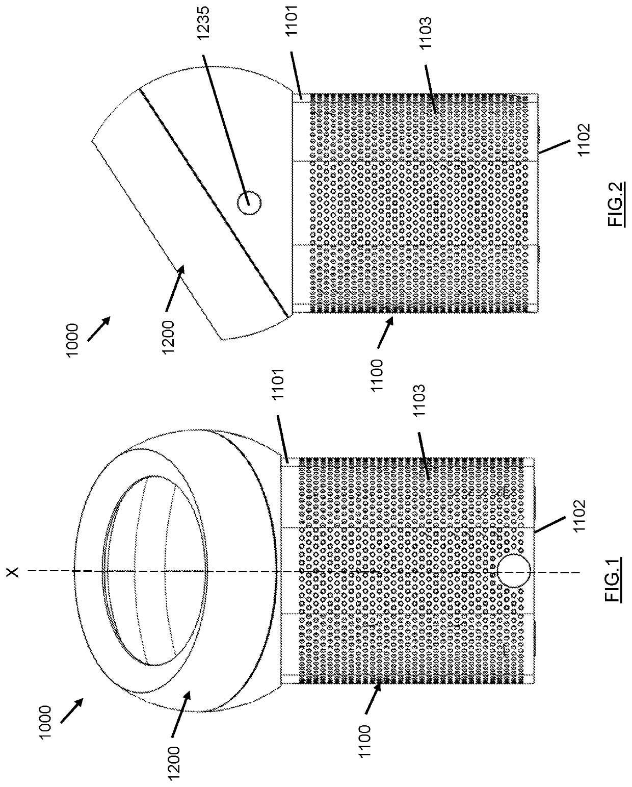
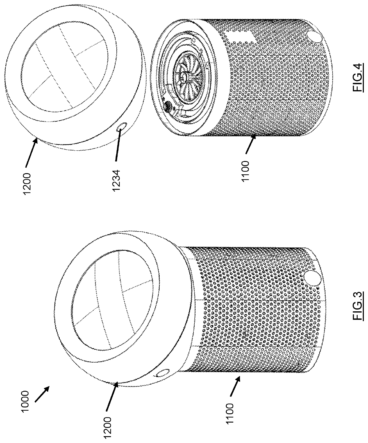
[0056]There will now be described a nozzle for a fan assembly which is capable of receiving input of a single air flow, e.g. from a single air supply source, and manipulating the air flow such that the direction of the air flow emitted from the nozzle may be changed without the need to tilt either the nozzle or the fan assembly to which the nozzle is attached. The term “fan assembly” as used herein refers to a fan assembly configured to generate and deliver an airflow for the purposes of thermal comfort and / or environmental or climate control. Such a fan assembly may be capable of generating one or more of a dehumidified airflow, a humidified airflow, a purified airflow, a filtered airflow, a cooled airflow, and a heated airflow. However, the fan assembly could equally be suitable for generating an airflow for other purposes, such as in a hair dryer or other hair care appliance.

[0057]The nozzle comprises an air inlet, a first air outlet for emitting an air flow and a second air outl...


PUM


Abstract

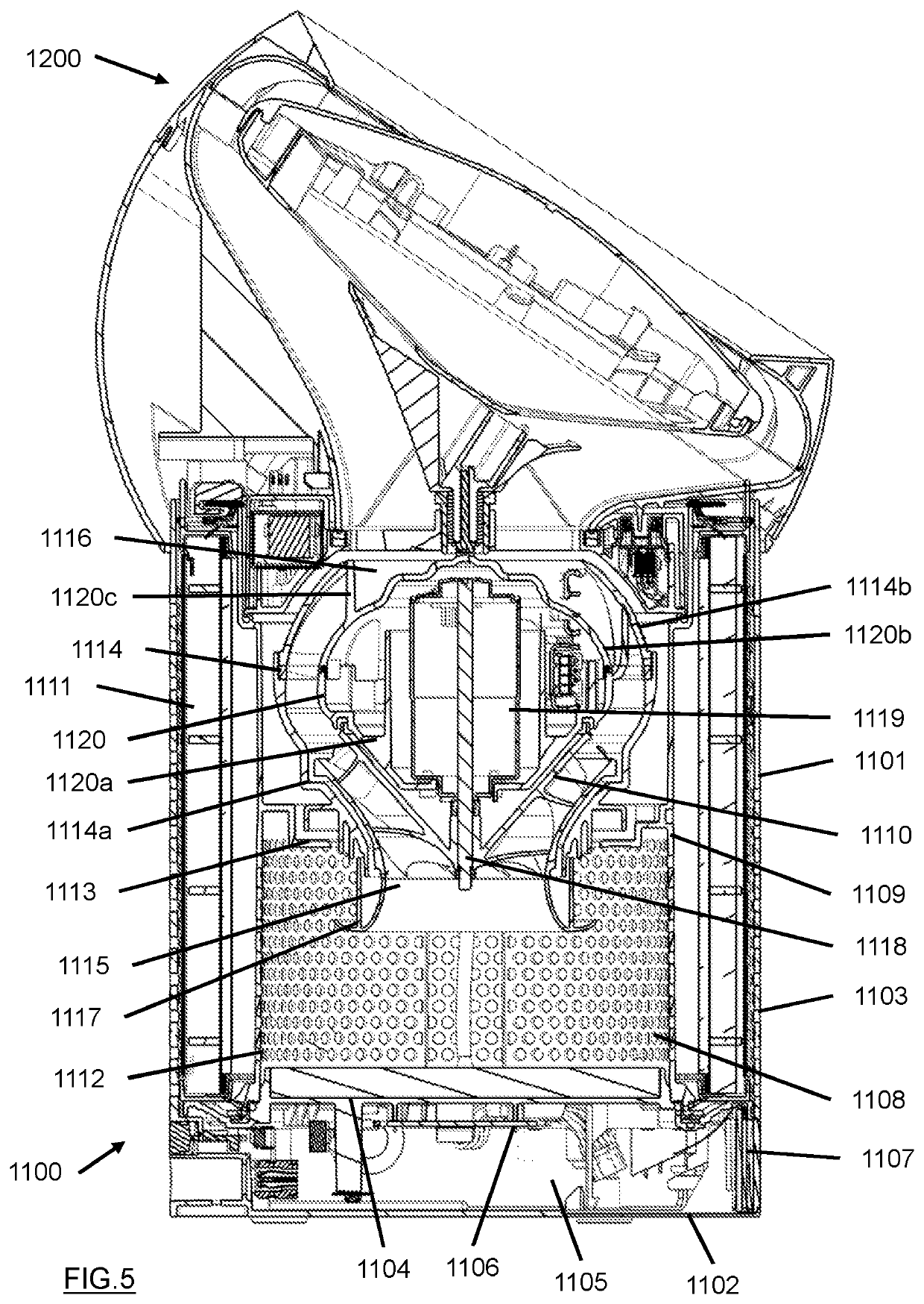
There is provided a fan assembly comprising a fan body, a motor-driven impeller contained within the fan body and arranged to generate an air flow, a nozzle comprising a nozzle body having an air inlet arranged to receive the air flow from the fan body and one or more air outlets arranged to emit the airflow from the fan assembly. The fan assembly further comprises a nozzle retaining mechanism for releasably retaining the nozzle on the fan body, and a rotation mechanism for rotating the nozzle body relative to the fan body. The nozzle rotation mechanism comprises a rotation motor arranged to drive a drive member and a driven member that is arranged to be driven by the drive member to rotate around a rotation axis, wherein the nozzle body comprises the driven member and the fan body comprises the rotation motor and the drive member.

Description

REFERENCE TO RELATED APPLICATIONS[0001]This application is a national stage application under 35 USC 371 of International Application No. PCT / GB2019 / 052832, filed Oct. 8, 2019, which claims the priority of United Kingdom Application No. 1817849.1, filed Nov. 1, 2018, the entire contents of each of which are incorporated herein by reference.FIELD OF THE DISCLOSURE[0002]The present invention relates to a fan assembly and a nozzle for such a fan assembly.BACKGROUND OF THE DISCLOSURE[0003]A conventional domestic fan typically includes a set of blades or vanes mounted for rotation about an axis, and drive apparatus for rotating the set of blades to generate an air flow. The movement and circulation of the airflow creates a ‘wind chill’ or breeze and, as a result, the user experiences a cooling effect as heat is dissipated through convection and evaporation. The blades are generally located within a cage which allows an air flow to pass through the housing while preventing users from comi...

Claims


Application Information

Patent Timeline
IPC IPC(8): F04D29/56F04D19/00F24F8/108F24F8/158
CPCF04D29/563F04D19/002F04F5/16F04F5/461F04F5/48F04F5/46F04D29/703F24F8/158F24F8/108F04D25/10F24F8/10F15D1/08F24F13/06F04D29/403F04D29/263F05D2210/12
Inventor PEET, STEVEN EDUARDSTEWART, NEIL ANDREWFRYER, ROBERT JAMESJOUQUES, ADAM DANIELGIBSON-ROBINSON, VICTORIA ANNE DOROTHYWHITE, HARRIET REBECCABAKER, STEPHEN ANDREWDUVALL, THOMAS GREERCOLLINS, JACK DAVID
Owner DYSON TECH LTD
Learn More