Supercharge Your Innovation With Domain-Expert AI Agents!

AC Impedance Measurement Circuit with Calibration Function

a technology of impedance measurement and function, applied in the direction of ac/dc measuring bridge, diagnostic recording/measuring, instruments, etc., can solve the problems of affecting the measurement accuracy, making the accuracy of total impedance measurement results worse,

Active Publication Date: 2021-12-09
HYCON TECH
View PDF0 Cites 0 Cited by
  • Summary
  • Abstract
  • Description
  • Claims
  • Application Information

AI Technical Summary

Benefits of technology

The present invention is an AC impedance measurement circuit that includes a waveform generation circuit, a first amplifier, a second amplifier, a switch circuit, an impedance to be measured, a calibration impedance, a sampling circuit, and a reference impedance. The switch circuit includes a plurality of switches that connect the impedance to be measured or the calibration impedance to the second amplifier. The sampling circuit receives the clock signal and samples the output of the second amplifier. The invention allows for accurate and efficient measurement of AC impedance with improved accuracy and reliability.

Problems solved by technology

Although DC impedance measurement circuits are simpler, the disadvantage is that the measurement results include human skin impedances, which makes the accuracy of the total impedance measurement result worse.
In the above-mentioned prior arts, when the AC impedance measurement circuit is calibrated, it is necessary to connect two calibration impedances, which is inconvenient.
In addition, the switch connected in series with the object under test also has an impedance, which will affect the accuracy of the measurement result.

Method used


Image

  • AC Impedance Measurement Circuit with Calibration Function
  • AC Impedance Measurement Circuit with Calibration Function
  • AC Impedance Measurement Circuit with Calibration Function

Examples


first embodiment

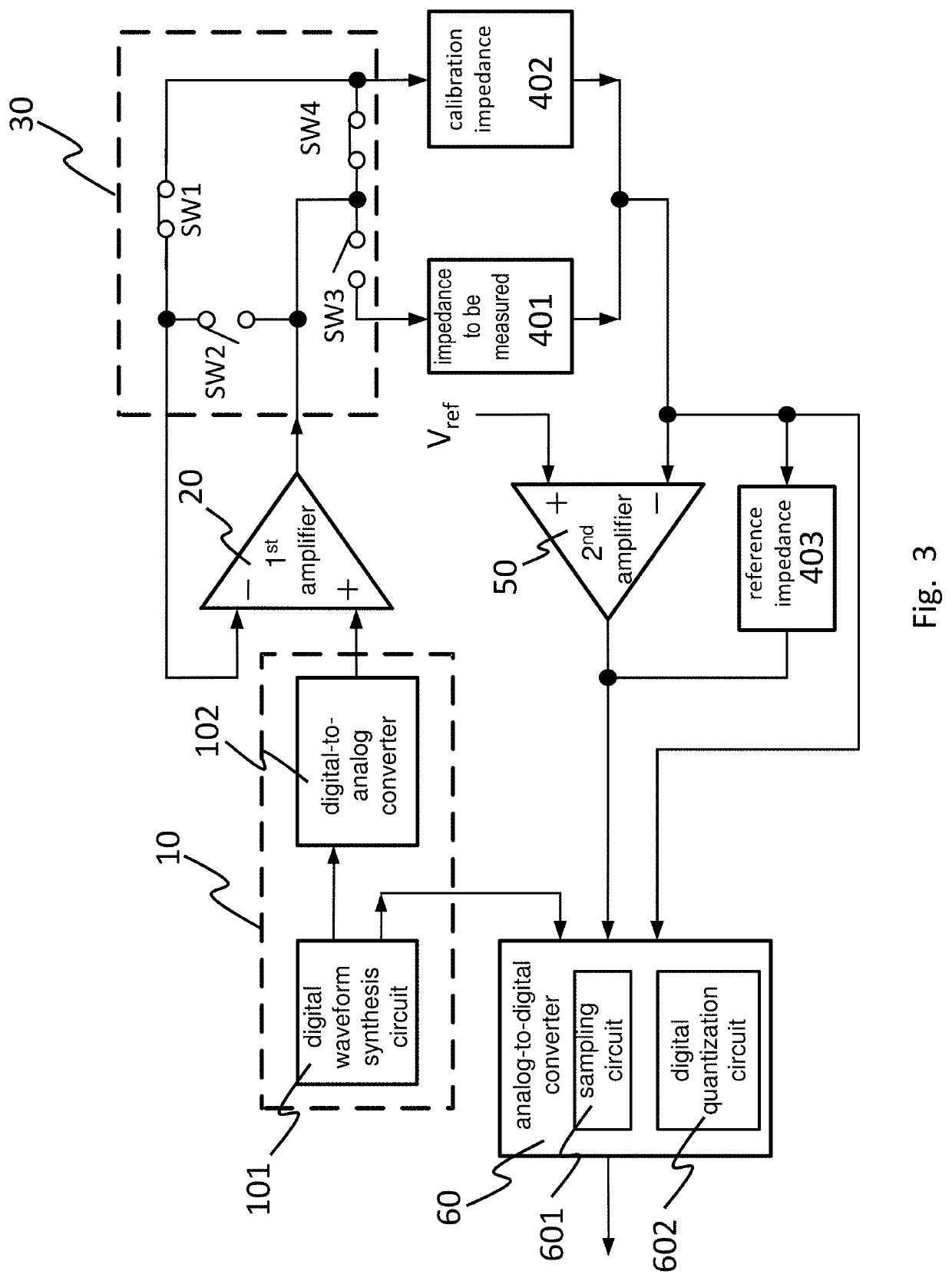
[0031]FIG. 1 shows the present invention. An AC impedance measurement circuit comprises: a waveform generation circuit 10 having a sinusoidal signal output for outputting a sinusoidal signal and a clock signal output for outputting a clock signal; a first amplifier 20 having a positive input connected to the sinusoidal signal output; a switch circuit 30 connected to a negative input of the first amplifier 20 and an output of the first amplifier 20; an impedance to be measured 401 and a calibration impedance 402, connected to the switch circuit 30; a second amplifier 50 having a positive input connected to a reference voltage and a negative input connected to the impedance to be measured 401 or the calibration impedance 402; a reference impedance 403 connected between the negative input of the second amplifier 50 and an output of the second amplifier 50; and an analog-to-digital converter 60 connected to the clock signal output of the waveform generation circuit 10 and both ends of t...

second embodiment

[0045]Referring to FIG. 6, which shows the present invention, another AC impedance measurement circuit comprises: a waveform generation circuit 10 for outputting a sinusoidal signal and a clock signal; a first amplifier 20 having a positive input connected to a sinusoidal signal output of the waveform generation circuit 10 and a negative input connected to a reference impedance 403 together with an output of the first amplifier 20; the reference impedance 403 having other end connected to a switch circuit 30 and a negative input of a second amplifier 50; the second amplifier 50 having a positive input connected to a reference voltage; an impedance to be measured 401 and a calibration impedance 402 connected between the switch circuit30 and an output of the second amplifier 50; and an analog-to-digital converter 60 for receiving the clock signal of the waveform generation circuit 10, output of the second amplifier 50, and voltage at the negative input of the second amplifier 50.

[0046...

third embodiment

[0055]Referring to FIG. 7, which shows the present invention, yet another AC impedance measurement circuit comprises: a waveform generation circuit 10 for outputting a sinusoidal signal and a clock signal; a reference impedance 403 having one end connected to a sinusoidal signal output of the waveform generation circuit 10 and other end connected to a switch circuit 30 and a negative input of a second amplifier 50; the second amplifier 50 having a positive input connected to a reference voltage; an impedance to be measured and a calibration impedance connected between the switch circuit 30 and an output of the second amplifier 50; and an analog-to-digital converter 60 for receiving the clock signal of the waveform generation circuit 10, output of the second amplifier 50, and voltage from the switch circuit 30.

[0056]According to the above-mentioned AC impedance measurement circuit, the switch circuit 30 comprises: a first switch SW1 connected between a negative input of the second am...


PUM


Abstract

The present invention discloses an AC impedance measurement circuit with a calibration function, which is characterized in that only one calibration impedance is needed, associated with a switch circuit. Based on the measurement results of the two calibration modes, an equivalent impedance of the switch circuit, circuit gain and phase offset can be calculated. Based on the above results, the equivalent impedance of the internal circuit is deducted from the measurement result of the measurement mode to accurately calculate an AC conductance and a phase of the AC conductance for impedance to be measured. In addition, by adjusting a phase difference between an input sine wave signal and a sampling clock signal, impedance of the same phase and impedance of the quadrature phase can be obtained, respectively, and the AC impedance and phase angle of the impedance to be measured can be calculated.

Description

FIELD OF THE INVENTION[0001]The present invention relates to an AC impedance measurement circuit. More specifically, the present invention relates to a measurement circuit with a calibration function to calculate an equivalent impedance of a switch circuit in order to compensate measurement result.BACKGROUND OF THE INVENTION[0002]AC impedance measurement circuits are widely used in human body impedance measurement, allowing users to pay attention to their own body fat content, and then more accurately grasp their own health status. Although DC impedance measurement circuits are simpler, the disadvantage is that the measurement results include human skin impedances, which makes the accuracy of the total impedance measurement result worse. AC impedance measurement circuits can reduce the influence of skin impedance on measurement result, and accurately analyze the equivalent AC impedance and phase characteristics of human body.[0003]Chinese Patent No. 105,662,411 discloses an AC imped...

Claims


Application Information

Patent Timeline
IPC IPC(8): G01R27/02G01R35/00G01R15/00G01R17/10
CPCG01R27/02G01R17/105G01R15/002G01R35/007G01R27/14G01R35/005A61B5/053A61B2560/0223
Inventor CHAO, PO-YINLEE, SHUI-CHUCHUANG, YU-WEI
Owner HYCON TECH
Features
  • R&D
  • Intellectual Property
  • Life Sciences
  • Materials
  • Tech Scout
  • Unparalleled Data Quality
  • Higher Quality Content
  • 60% Fewer Hallucinations
Learn More