Drive unit and electrically assisted vehicle

a technology of driving gear and drive unit, which is applied in the direction of vehicle components, rider propulsion, transportation and packaging, etc., can solve the problems of further the difficulty of shortening the width of the drive unit in the axial direction, etc., and achieves the improvement of the degree of freedom of positional arrangement, the effect of reducing the diameter of the driven gear and reducing the size of the drive uni

Active Publication Date: 2021-12-16
YAMAHA MOTOR CO LTD
View PDF0 Cites 0 Cited by
  • Summary
  • Abstract
  • Description
  • Claims
  • Application Information

AI Technical Summary

Benefits of technology

[0041]The electrically assisted vehicle includes the drive unit in which the driven gear on the pedal crank shaft has a small diameter so that the rear center length of the electrically assisted vehicle may be shortened.
[0042]The drive unit according to a preferred embodiment of the present invention uses the idle gear so that the diameter of the driven gear may be decre

Problems solved by technology

If a “two-axial decelerator” is located between the driven gear on the pedal crank shaft and the electric motor, it is difficult to shorten the width of the drive unit in the axial direction.
The use

Method used


Image

  • Drive unit and electrically assisted vehicle
  • Drive unit and electrically assisted vehicle
  • Drive unit and electrically assisted vehicle

Examples


Embodiment Construction

[0052]Hereinafter, drive units and electrically assisted vehicles including the drive units according to preferred embodiments of the present invention will be described with reference to the drawings. In the description of the preferred embodiments, like components will bear like reference signs, and overlapping descriptions will be omitted. In the preferred embodiments of the present invention, “front”, “rear”, “left”, “right”, “up” and “down” respectively refer to “front”, “rear”, “left”, “right”, “up” and “down” based on a state where a rider is sitting on a saddle (seat) of the electrically assisted vehicle while facing a handle. The following preferred embodiments are merely illustrative, and the present invention is not limited to the following preferred embodiments in any way.

Electrically Assisted Bicycle

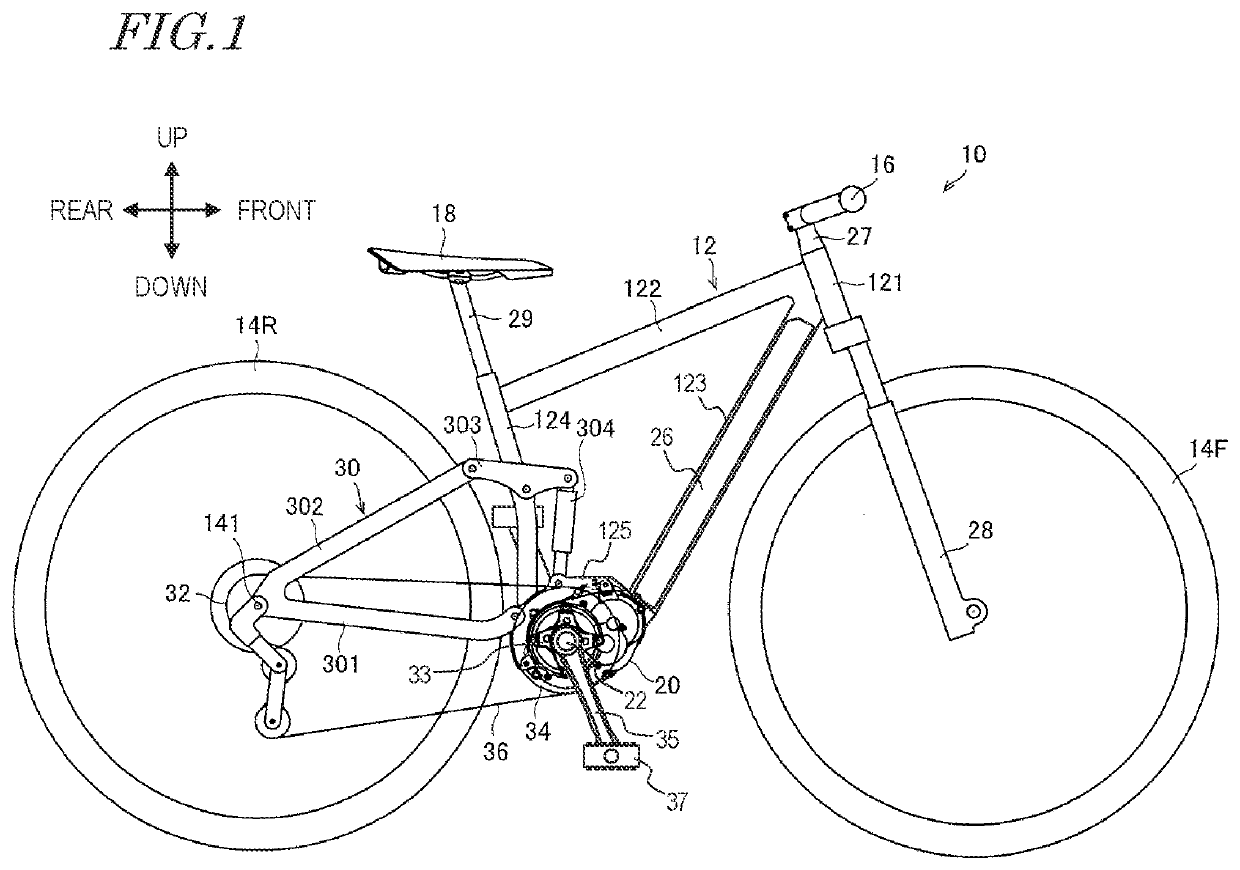
[0053]With reference to FIG. 1, an electrically assisted bicycle 10 as an example of electrically assisted vehicle according to a preferred embodiment of the present inventi...


PUM


Abstract

A drive unit includes an electric motor including an output shaft including an output gear; a pedal crank shaft extending through a housing, rotatably supported by the housing, and including a driven gear; and a transmission to transmit a torque of the output gear of the electric motor to the driven gear. The transmission includes a decelerator rotatably supported by the housing, and an idle gear rotatably supported by the housing. The decelerator increases the torque of the output shaft of the electric motor, and the increased torque is transmitted to the driven gear via the idle gear.

Description

CROSS REFERENCE TO RELATED APPLICATIONS[0001]This application claims the benefit of priority to Japanese Patent Application No. 2020-081834 filed on May 7, 2020. The entire contents of this application are hereby incorporated herein by reference.BACKGROUND OF THE INVENTION1. Field of the Invention[0002]The present invention relates to a drive unit attachable to a vehicle frame of an electrically assisted vehicle, and also to an electrically assisted vehicle including such a drive unit.2. Description of the Related Art[0003]An example of vehicle movable in accordance with power generated by a power source is an electrically assisted bicycle by which power provided by a rider pedaling the bicycle is assisted by an electric motor (see, for example, Japanese Laid-Open Patent Publication No. 2014-196080). An electrically assisted bicycle causes the electric motor to generate drive power in accordance with human power applied by the rider to pedals. Thus, the electrically assisted bicycle...

Claims


Application Information

Patent Timeline
IPC IPC(8): B62M6/55B62M6/45
CPCB62M6/55B62M6/45
Inventor USAMI, TOMOHIRO
Owner YAMAHA MOTOR CO LTD
Why Eureka
Try Eureka