Supercharge Your Innovation With Domain-Expert AI Agents!

System frequency detector

a detector and system frequency technology, applied in the direction of frequency to phase shift conversion, frequency to amplitude conversion, frequency measurement arrangement, etc., can solve the problems of difficult rapid output tracking for a change of system frequency, temporary oscillation of calculated frequency, etc., and achieve the effect of suppressing erroneous detection of system frequency and quick tracking

Pending Publication Date: 2021-12-30
TOSHIBA MITSUBISHI-ELECTRIC IND SYST CORP
View PDF0 Cites 0 Cited by
  • Summary
  • Abstract
  • Description
  • Claims
  • Application Information

AI Technical Summary

Benefits of technology

The invention provides a system frequency detector that can quickly track changes in the system frequency and prevent incorrect detection of the frequency even during system disturbances.

Problems solved by technology

Therefore, for example, rapid output tracking for a change of the system frequency such as tracking with a delay of 40 msec or less, etc., is difficult.
However, there are cases where the calculated frequency temporarily oscillates greatly when a phase jump occurs in the system voltage.

Method used


Image

  • System frequency detector
  • System frequency detector
  • System frequency detector

Examples


first embodiment

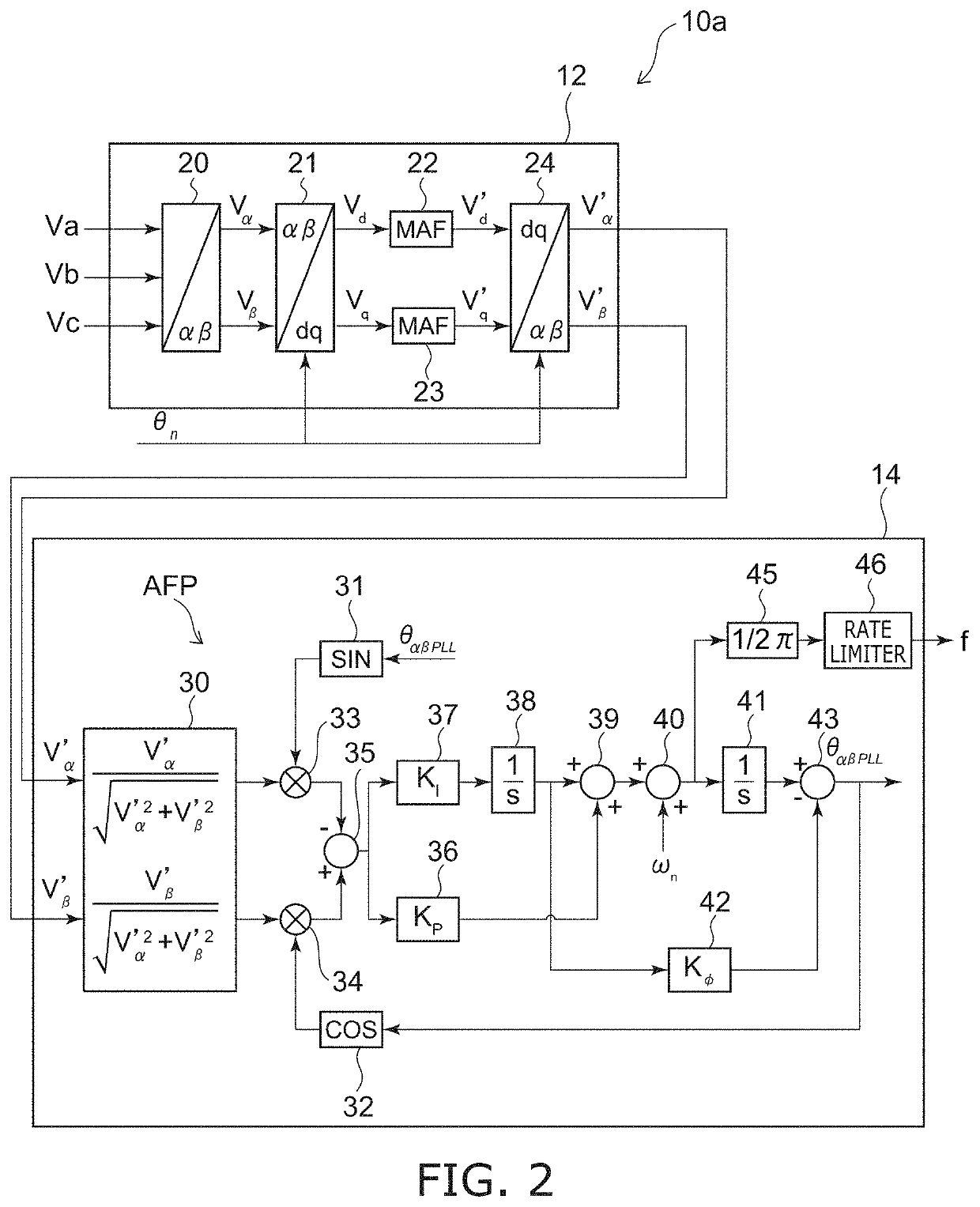
[0024]FIG. 1 is a block diagram schematically illustrating a system frequency detector according to a first embodiment.

[0025]As illustrated in FIG. 1, the system frequency detector 10 includes an orthogonal coordinate signal generator 12 and a frequency calculator 14. The system frequency detector 10 detects the system frequency of a power system of three-phase alternating current power.

[0026]For example, the system frequency detector 10 is used in a power conversion device in which a distributed power source such as solar power generation, wind power generation, or the like is connected to a power system, etc. However, applications of the system frequency detector 10 are not limited thereto. The system frequency detector 10 can be used in any device in which it is necessary to detect the system frequency of a power system of three-phase alternating current power.

[0027]The orthogonal coordinate signal generator 12 generates orthogonal two-phase voltage signals Vα′ and Vβ′ from three...

second embodiment

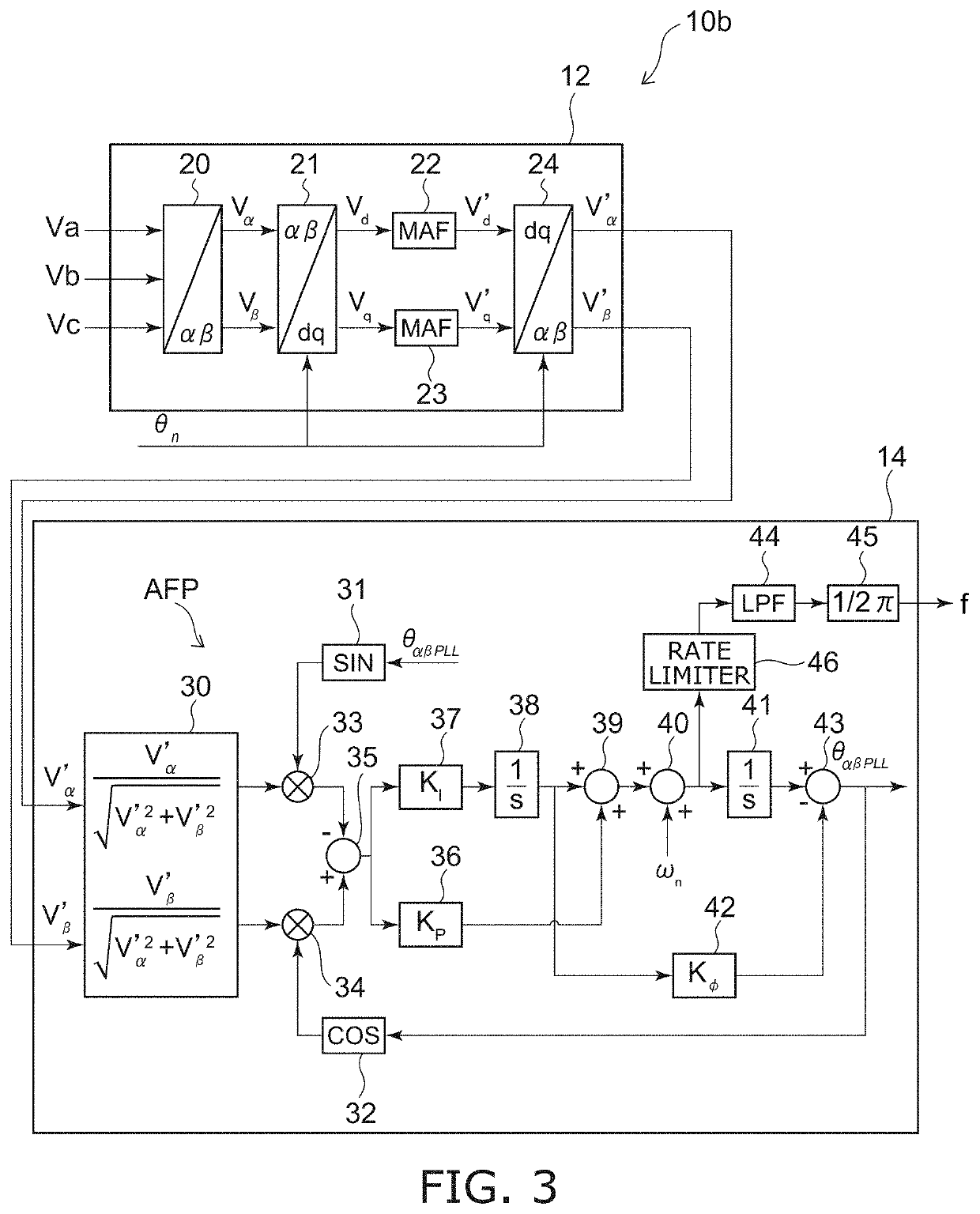
[0061]FIG. 3 is a block diagram schematically illustrating a system frequency detector according to a second embodiment.

[0062]In the system frequency detector 10b as illustrated in FIG. 3, the frequency calculator 14 further includes a low-pass filter 44. The low-pass filter 44 is provided in series with the arithmetic unit 45. For example, the low-pass filter 44 is provided between the arithmetic unit 45 and the rate limiter 46.

[0063]The low-pass filter 44 suppresses the high frequency components of the angular frequency ω. The low-pass filter 44 attenuates frequency components of the angular frequency ω that are greater than a prescribed frequency. In other words, the low-pass filter 44 suppresses an abrupt fluctuation of the angular frequency ω. For example, the low-pass filter 44 may use a moving average filter. The low-pass filter 44 inputs, to the arithmetic unit 45, the angular frequency ω after the high frequency components are suppressed.

[0064]The low-pass filter 44 is prov...

third embodiment

[0067]FIG. 4 is a block diagram schematically illustrating a system frequency detector according to a third embodiment.

[0068]In the system frequency detector 10c as illustrated in FIG. 4, the frequency calculator 14 further includes subtractors 47 and 48. The subtractor 47 is connected to the input and output sides of the rate limiter 46. The subtractor 47 subtracts the output value of the rate limiter 46 from the input value of the rate limiter 46. In other words, the subtractor 47 calculates the difference between the input value and the output value of the rate limiter 46. The difference between the output value of the rate limiter 46 and the input value of the rate limiter 46 is calculated by the subtractor 47 when the calculated value of the angular frequency ω abruptly increases, the angular frequency ω is limited by the rate limiter 46, and the output value of the rate limiter 46 becomes less than the input value of the rate limiter 46. The subtractor 47 inputs the calculatio...


PUM


Abstract

A system frequency detector includes an orthogonal coordinate signal generator generating an orthogonal two-phase voltage signal from a three-phase voltage signal of three-phase alternating current power by converting the three-phase voltage signal into a two-phase voltage signal orthogonal to the three-phase voltage signal, converting the two-phase voltage signal into a voltage signal of a rotating coordinate system, calculating a moving average of the voltage signal of the rotating coordinate system, and performing an inverse transformation of the voltage signal of the rotating coordinate system after calculating the moving average. A frequency calculator calculates an angular frequency based on the two-phase voltage signal, and an arithmetic unit calculates a system frequency of the power system from the angular frequency. The frequency calculator includes a rate limiter in series with the arithmetic unit, the rate limiter limiting a change of the system frequency equal to or greater than a prescribed change rate.

Description

TECHNICAL FIELD[0001]Embodiments of the invention relate to a system frequency detector.BACKGROUND ART[0002]A zero crossing point detection-type frequency calculation is known as a technique of detecting a system frequency of a power system. The zero crossing point detection-type frequency calculation can take measurement data only in intervals synchronized with the system frequency; ordinarily, a filter of a relatively long time constant of 200 msec or more has been provided to acquire resistance to system disturbances. Therefore, for example, rapid output tracking for a change of the system frequency such as tracking with a delay of 40 msec or less, etc., is difficult.[0003]Also, a frequency calculation using PLL (Phase Locked Loop) using a DQ transformation also is known. Such a frequency calculation using PLL can be used as a good frequency detector if there is no trouble at the power system side, and the system frequency can be tracked more quickly than the zero crossing point ...

Claims


Application Information

Patent Timeline
IPC IPC(8): G01R23/06G01R23/15
CPCG01R23/06G01R23/15G01R23/02G01R23/12
Inventor MITSUGI, YASUAKISHIGEMASA, TAKASHI
Owner TOSHIBA MITSUBISHI-ELECTRIC IND SYST CORP
Features
  • R&D
  • Intellectual Property
  • Life Sciences
  • Materials
  • Tech Scout
  • Unparalleled Data Quality
  • Higher Quality Content
  • 60% Fewer Hallucinations
Learn More