User station for a serial bus system, and method for transmitting a message in a serial bus system

a serial bus system and user station technology, applied in data switching networks, high-level techniques, instruments, etc., can solve the problems of low data overhead, no longer reliable interoperability of user stations of bus systems with higher data bit rates than can fd, and low data rate or bit rate. , the effect of increasing the quantity of useful data per fram

Active Publication Date: 2021-12-30
ROBERT BOSCH GMBH
View PDF10 Cites 4 Cited by
  • Summary
  • Abstract
  • Description
  • Claims
  • Application Information

AI Technical Summary

Benefits of technology

[0006]An object of the present invention is to provide a user station for a serial bus system, and a method for transmitting a message in a serial bus system, which solve the above-mentioned problems. In particular, an object of the present invention to provide a user station for a serial bus system, and a method for transmitting a message in a serial bus system in which a high data rate or bit rate and an increase in the quantity of the useful data per frame may be achieved with few sources of error.
[0008]By use of the user station, it is possible in particular to carry out a reliable bit rate switchover from the arbitration phase to the data phase and a reliable bit rate switchover from the data phase to the arbitration phase, even when there is a significant increase in the bit rate in the data phase compared to the arbitration phase. This is also true when in addition, different physical layers are used in the arbitration phase and the data phase.
[0010]In accordance with an example embodiment of the present invention, it is also advantageous that for the switchover of the bit rates, only a very short bit sequence, namely, only two bits or up to four bits, is required. This results in only a very low data overhead, so that the speed of the communication between user stations of the bus system is only minimally affected.
[0011]In accordance with an example embodiment of the present invention, an additional advantage is that the bit rate switchover is independent of the sampling positions of the user stations. This results in greater robustness and fewer error sources in the application.
[0012]In accordance with an example embodiment of the present invention, the method carried out by the user station also takes into account that for the duration of the data phase, it may be necessary to switch the physical layer from the physical layer in the arbitration phase over to a different physical layer. It is possible, if necessary, to also operate user stations in the bus system that carry out no switchover of the physical layer between the arbitration phase and the data phase. A seamless migration path from CAN FD toward CAN NG is thus possible.
[0017]In accordance with an example embodiment of the present invention, the bit rate switchover unit is possibly designed to append, in the predetermined bit sequence, a buffer time to the bit of the first communication phase or the bit of the second communication phase, a transceiver device of the user station being designed to generate a first bus state for a first digital data state of the messages, and to generate a second bus state for the second digital data state of the messages, at the first bit rate in such a way that the second bus state can overwrite the first bus state, and the transceiver device, for transmitting at the second bit rate, being designed to generate different bus states in such a way that the bus states for the different digital data states of the messages cannot overwrite one another.

Problems solved by technology

However, the recessive bus state is set only relatively slowly by terminating resistors of the bus system.
As a result, the interoperability of user stations of a bus system with higher data bit rates than with CAN FD are no longer reliably ensured.
This results in only a very low data overhead, so that the speed of the communication between user stations of the bus system is only minimally affected.

Method used


Image

  • User station for a serial bus system, and method for transmitting a message in a serial bus system
  • User station for a serial bus system, and method for transmitting a message in a serial bus system
  • User station for a serial bus system, and method for transmitting a message in a serial bus system

Examples


Embodiment Construction

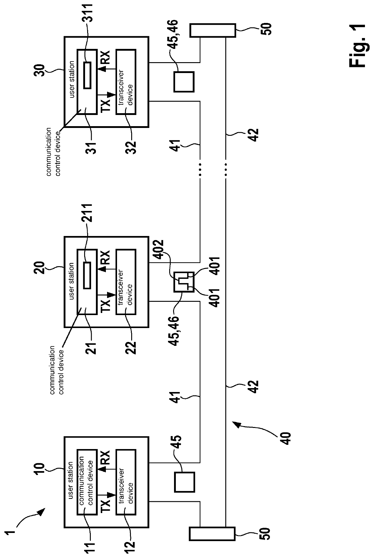
[0035]FIG. 1 shows as an example a bus system 1 that is in particular the basis for a conventional CAN bus system, a CAN FD bus system, a CAN FD successor bus system, also referred to as a

[0036]CAN NG bus system, and / or modifications thereof, as described below. Bus system 1 may be used in a vehicle, in particular a motor vehicle, an aircraft, etc., or in a hospital, and so forth.

[0037]In FIG. 1, bus system 1 includes a plurality of user stations 10, 20, 30, each of which is connected to a first bus wire 41 and a second bus wire 42 at a bus 40. Bus 40 at both of its ends is closed off via terminating resistors 50. Bus wires 41, 42 may also be referred to as CAN_H and CAN_L and, using a TX signal in the transmission state, are used for electrical signal transfer after coupling in the dominant levels or states 401, or generating or actively driving recessive levels or states 402. States 401, 402 are shown in a highly schematic manner only for user station 20. States 401, 402 correspon...


PUM


Abstract

A user station for a serial bus system and a method for transmitting a message in a serial bus system. The user station includes a communication control device for transmitting messages to a bus of the bus system and / or for receiving messages from the bus of the bus system, and a bit rate switchover unit for switching over a bit rate of the messages from a first bit rate in a first communication phase to a second bit rate for a second communication phase. The bit rate switching unit is designed to switch the bit rate from the first bit rate over to the second bit rate, due to an edge of a predetermined bit sequence that includes one bit of the first communication phase and one bit of the second communication phase.

Description

FIELD[0001]The present invention relates to a user station for a serial bus system, and a method for transmitting a message in a serial bus system, via which a communication in the bus system is selectively possible according to a first communication protocol or a second communication protocol, the communication according to the second communication protocol taking place at a much higher bit rate, and if necessary, with a different physical layer, than with the first communication protocol, so that a specific bit rate switchover is carried out.BACKGROUND INFORMATION[0002]For the communication between sensors and control units, for example in vehicles, more and more frequently a bus system is used in which data are transferred as messages under the ISO 11898-1:2015 standard, as a CAN protocol specification with CAN FD. The messages are transferred between the user stations of the bus system, such as the sensor, control unit, transducer, etc. In the introduction phase, at the present ...

Claims


Application Information

Patent Timeline
Patent Type & Authority Applications(United States)
IPC IPC(8): G06F13/42G06F13/36
CPCG06F13/4282G06F13/36H04L12/4135H04L2012/40215H04L12/4013H04L12/407H04L12/40H04L12/413Y02D30/50
Inventor MUTTER, ARTHURHARTWICH, FLORIAN
Owner ROBERT BOSCH GMBH
Why Eureka
Try Eureka