
Rotor with superconducting winding for continuous current mode operation

Pending Publication Date: 2021-12-30
SIEMENS AG
View PDF3 Cites 0 Cited by
  • Summary
  • Abstract
  • Description
  • Claims
  • Application Information

AI Technical Summary

Benefits of technology

The rotor described in this patent has a special conductor section that allows for the supply of current without changing the function of the rotor winding. This conductor section is separate from the rotor winding and is located in a different position on the rotor. This separation results in minimal heating of the rotor winding, which helps to maintain the superconducting state. The separate arrangement of the conductor section also reduces the need for a current source, which results in a higher power density for the rotor during operation.

Problems solved by technology

This solution is disadvantageous in that, in this case, a comparatively sophisticated transmission device is required to transmit the current from the stationary system to the rotating rotor winding.
However, both variants are comparatively complex, and each require at least one option for supplying the exciting current which is in permanent use during the operation of the electrical machine.
Such a conductor material results in corresponding ohmic losses which, depending on the machine size, may be in the range of several kilowatts to megawatts.
However, this additional weight contribution is disadvantageous for developing an electrical machine with a very high-power density.
However, the solution described therein is disadvantageous in that a significant part of the rotor winding has to be heated to open the continuous current switch.
Therefore, a large amount of heat is generated in the region of the rotor winding, which firstly has to be dissipated again prior to use in the superconducting continuous current mode.
Moreover, as a result of the local heating, thermal gradients are produced in the coil which may lead to damage of the superconductor as a result of the associated mechanical stresses.
All in all, an undesired asymmetry in the construction of the rotor winding is generated as a result of using a specific winding section as a switch.
A further disadvantage of using one or more magnetic poles as a switch includes that the supply current only flows in the remaining poles of the winding during the power supply procedure and the magnetic energy has to be distributed to all poles after the termination of the power supply.
This leads to an undesirably high current load on all components during the power supply procedure.

Method used


Image

  • Rotor with superconducting winding for continuous current mode operation
  • Rotor with superconducting winding for continuous current mode operation
  • Rotor with superconducting winding for continuous current mode operation

Examples


Embodiment Construction

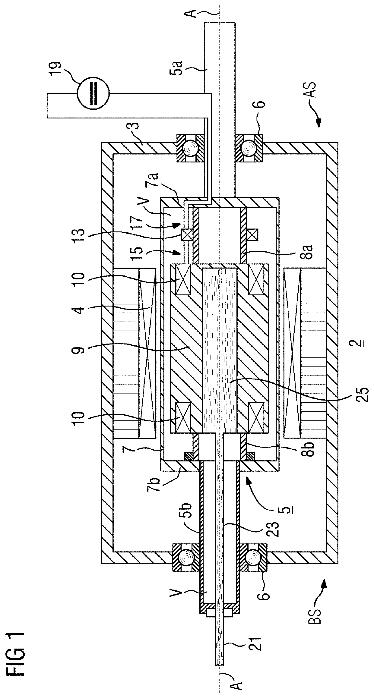
[0066]FIG. 1 depicts an electrical machine 2 according to a first exemplary embodiment in a schematic longitudinal section, e.g., along the central machine axis A. The machine 2 includes a stationary machine outer housing 3, which is at room temperature and has a stator winding 4 therein. Within this (for example, evacuable) outer housing and surrounded by the stator winding 4, a rotor 5 is mounted in bearings 6 such that it is rotatable about an axis of rotation A, which rotor includes, on its drive side AS, a solid axial rotor shaft part 5a mounted in the corresponding bearing. The rotor has a rotor outer housing 7 which is configured as a vacuum vessel and in which a winding carrier 9 with a superconducting rotor winding 10 is mounted. Serving this purpose, on the drive side AS, there is a (first) rigid, tubular connecting element 8a between the winding carrier 9 and a disk-shaped side part 7a, fixedly connected to the rotor shaft part 5a, of the rotor outer housing 7. The substa...


PUM


Abstract

A rotor for an electrical machine is disclosed herein. The rotor includes a rotor housing, a winding carrier arranged therein, at least one first axial connecting element mechanically interconnecting the winding carrier and the rotor housing, and a superconducting rotor winding configured to produce a magnetic field. The rotor winding is mechanically retained by the winding carrier and is part of a self-contained circuit inside the rotor in which circuit a continuous current may flow. The self-contained circuit has a continuous current switch with a switchable conductor section that may be switched between a superconducting state and a normally conducting state. The switchable conductor section is arranged on the first axial connecting element. A machine including the rotor and a method for operating the rotor is also disclosed herein.

Description

[0001]The present patent document is a § 371 nationalization of PCT Application Serial No. PCT / EP2019 / 072198, filed Aug. 20, 2019, designating the United States, which is hereby incorporated by reference, and this patent document also claims the benefit of German Patent Application No. 10 2018 214 049.9, filed Aug. 21, 2018, and German Patent Application No. 10 2018 215 917.3, filed Sep. 19, 2018, which are also hereby incorporated by reference.TECHNICAL FIELD[0002]The present disclosure relates to a rotor for an electrical machine having a superconducting rotor winding, wherein the superconducting rotor winding is part of a self-contained circuit in which a continuous current is configured to flow. The closed circuit has a continuous current switch having a switchable conductor section which may be switched between a superconducting state and a normally conducting state. The disclosure furthermore relates to an electrical machine having such a rotor and a method for operating such ...

Claims


Application Information

Patent Timeline
IPC IPC(8): H02K55/04
CPCH02K55/04H01F6/008Y02E40/60H10N60/355
Inventor GRUNDMANN, JÖRNOOMEN, MARIJN PIETERVAN HASSELT, PETER
Owner SIEMENS AG
Features
  • Generate Ideas
  • Intellectual Property
  • Life Sciences
  • Materials
  • Tech Scout
  • Unparalleled Data Quality
  • Higher Quality Content
  • 60% Fewer Hallucinations
Learn More