
Multiplexer, front end module, and communication device

a technology of front end module and multi-channel filter, which is applied in the field of multi-channel filter, can solve the problems of not being able to achieve the optimization of bandpass characteristics of another filter and the optimization of bandpass characteristics of a filter at the same tim

Pending Publication Date: 2021-12-30
MURATA MFG CO LTD
View PDF0 Cites 1 Cited by
  • Summary
  • Abstract
  • Description
  • Claims
  • Application Information

AI Technical Summary

Benefits of technology

The patent is about a device called a multiplexer that can optimize the impedance of filters connected to a common terminal at the same time. This leads to improved performance in high-speed communication. A front end module including this multiplexer and a communication device including it are also disclosed. The technical effect is faster and more reliable data transfer.

Problems solved by technology

Therefore, optimization of bandpass characteristics of a filter and optimization of bandpass characteristics of another filter might not be achieved at the same time.

Method used


Image

  • Multiplexer, front end module, and communication device
  • Multiplexer, front end module, and communication device
  • Multiplexer, front end module, and communication device

Examples


first embodiment

[1.1 Configuration of Multiplexer 1, Front End Module 7, and Communication Device 5)

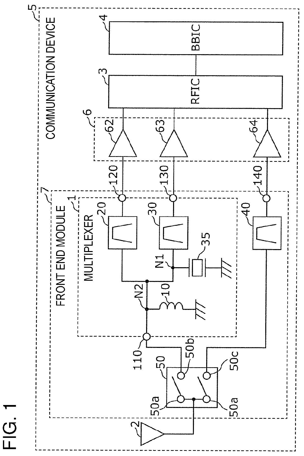
[0024]FIG. 1 is a circuit configuration diagram of a multiplexer 1, a front end module 7, and a communication device 5 according to a first embodiment. As illustrated in FIG. 1, the communication device 5 includes the front end module 7, an antenna 2, a reception amplification circuit 6, an RF signal processing circuit (RFIC) 3, and a baseband signal processing circuit (BBIC) 4.

[0025]The RFIC 3 is an RF signal processing circuit that processes a high frequency signal transmitted and received by the antenna 2. Specifically, the RFIC 3 performs signal processing, via down conversion or the like, on a high frequency signal input from the antenna 2 through the front end module 7 and the reception amplification circuit 6(in this case, a high-frequency reception signal) and outputs a reception signal generated by the signal processing to the BBIC 4. Furthermore, the RFIC 3 may perform signal processing, vi...

second embodiment

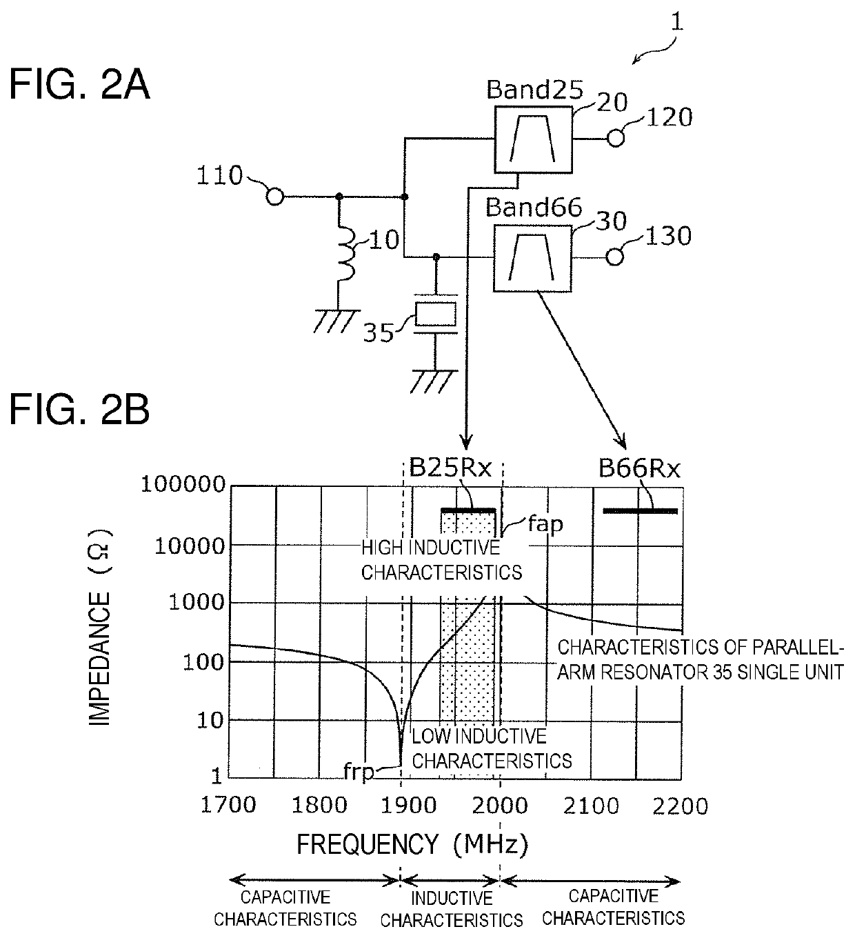
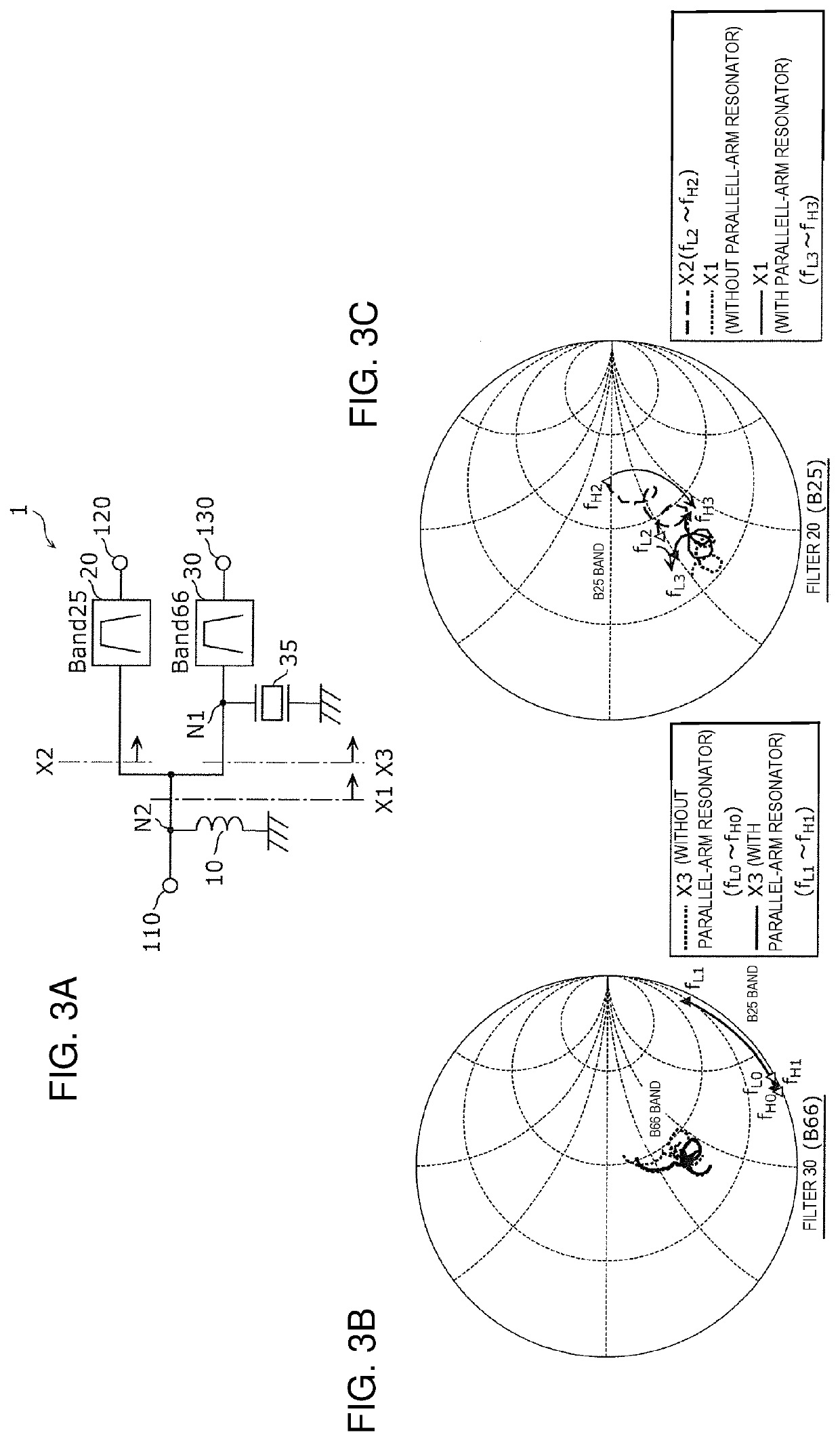
[0067]In the first embodiment, optimization of impedances of the filters 20 and 30 is achieved by making the inductive region of the parallel-arm resonator 35 overlap with the pass band of the filter 20. However, in this embodiment, optimization of impedances of the filters 20 and 30 is achieved by making a capacitive region of the parallel-arm resonator 35 overlap with the pass band of the filter 20.

[2.1 Configuration of Multiplexer 1B]

[0068]FIG. 7A includes a circuit configuration diagram of a multiplexer lB according to a second embodiment and FIG. 7B includes impedance characteristics of a parallel-arm resonator 35. As illustrated in FIG. 7A, the multiplexer lB includes a common terminal 110 (first common terminal), a reception output terminal (first input / output terminal) 120, a reception output terminal (second input / output terminal) 130, filters 20 and 30, the parallel-arm resonator 35, and an inductor 37.

[0069]The filter 20 is an example of a first filter. The filter 20 is c...


PUM


Abstract

A multiplexer includes a common terminal, reception output terminals (120 and 130), a filter (20) that is connected between the common terminal and the reception output terminal (120), a filter (30) that is connected between the common terminal and the reception output terminal (130) and has a pass band different from a pass band of the filter (20), and an impedance matching circuit that is arranged between the common terminal and the filter (30). The impedance matching circuit includes a parallel-arm resonator that is connected between a node (N1) on a path connecting the common terminal to the filter (30) and a ground.

Description

CROSS REFERENCE TO RELATED APPLICATIONS[0001]This is a continuation of International Application No. PCT / JP2020 / 010521 filed on Mar. 11, 2020 which claims priority from Japanese Patent Application No. 2019-046269 filed on Mar. 13, 2019. The contents of these applications are incorporated herein by reference in their entireties.BACKGROUNDTechnical Field[0002]The present disclosure relates to a multiplexer, a front end module including the multiplexer, and a communication device including the multiplexer.[0003]Multiplexers that transmit, receive, or transmit and receive two or more high frequency signals having different frequency bands at the same time with low loss have been required.[0004]In Patent Document 1, a multiplexer with a configuration in which a plurality of filters are connected to a common terminal and an inductor is arranged between one of the plurality of filters and the common terminal is described. Specifically, an impedance of a predetermined pass band of the one o...

Claims


Application Information

Patent Timeline
IPC IPC(8): H04B1/00H03H9/64H03H9/72H04B1/18
CPCH04B1/0057H04B1/18H03H9/72H03H9/6433H04B1/00H04B1/40H03H9/725H03H9/706H03H7/463H03H9/542
Inventor TANI, MASAKAZU
Owner MURATA MFG CO LTD
Learn More