Temperature resistant carbon coatings

a carbon coating, temperature resistant technology, applied in the direction of ion implantation coating, superimposed coating process, coating, etc., can solve the problems of high temperature, limited life of moulds, and inability to meet the requirements of diamond-like carbon coatings

Pending Publication Date: 2022-01-06
NANOFILM TECH INT LTD
View PDF5 Cites 0 Cited by
  • Summary
  • Abstract
  • Description
  • Claims
  • Application Information

AI Technical Summary

Problems solved by technology

However, for these applications, conventional diamond-like carbon coatings do not meet these requirements.
In particular, hydrogenated DLCs are typically unstable at higher temperatures as they emit hydrogen gas.
However, these moulds have a limited lifetime.
This current process has the disadvantage that the graphite moulds have a short life span (usually in the environment of 650° C., the number of products that can be pressed is very limited).
In addition to this, the yield is low.
As a result of these problems and associated the high cost of this process, the application and cost of producing curved mobile phone screens is greatly affected.
However, a common problem with existing thermal printing heads is that the coatings wear quickly and therefore require frequent replacement.

Method used


Image

  • Temperature resistant carbon coatings
  • Temperature resistant carbon coatings

Examples


example 1

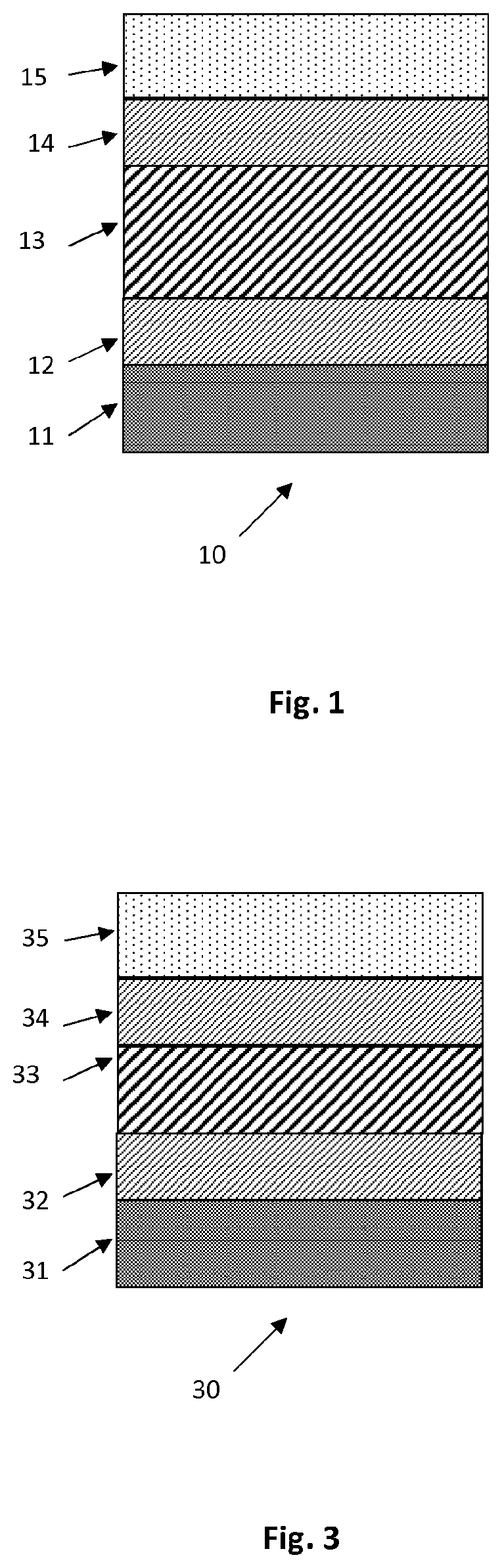
[0127]A first example of the coating of the invention (see FIG. 1, 10) was prepared as described below:

LayerThicknessTa-C (15)0.2μmSiC (14)0.15μmSi3N4 (13)0.5μmSiC (12)0.15μmGraphite Substrate (11)Total Thickness~1μm(determined by CAR2)

[0128]In summary, onto a sealed graphite substrate, a seed layer of SiC was sputtered, followed by subsequent layers in order of Si3N4, then SiC with the thicknesses in the tables above. Onto these intermediate layers was then deposited a ta-C coating using FCVA apparatus.

[0129]A commercially available sealant specially formulated for graphite surface (e.g. Resbond Graphite Sealer 931S-1) was sprayed onto the surface of a graphite glass lens mould and the sintered in a vacuum furnace at 1000° C. in order to seal the substrate.

[0130]Coating of the sealed graphite substrate was conducted using a large-scale ta-C coating equipment designed and manufactured by Nafeng. Firstly, the sealed graphite substrate was placed into the coating equipment chamber and...

example 2

[0132]A second example of the coating of the invention was prepared in an analogous manner to the coating of Example 1, with the structure shown in the table below.

LayerThicknessTa-C0.2μmTiC0.1μmAlTiN0.5μmSubstrateTotal Thickness~0.8μm(determined by CAR2)

example 3

[0133]A thermal printing head was coated (see FIG. 3, 30) in an analogous manner to the coating of Example 1, with the structure shown in the table below:

LayerThicknessTa-C (35)0.6 μmSiC (34)0.6 μmSi3N4 (33)0.5 μmSiC (32)0.6 μmSubstrate - SiO2-coated ceramic (with optional SiC coating) (31)

[0134]The performance of this coating was evaluated following exposure to 500° C. for two hours under atmospheric pressure.

[0135]Firstly, a sample of the coating was cut using a cross-hatch cutter (variable-length 1.5 mm2 cutter). A length of 3M610 tape was then applied to the cut surface of the coating and then peeled off. No coating was peeled off by the tape and hence this coating is well adhered to the substrate.

[0136]As an indication of the wear-resistance of the coating, a Taber abrasion test was conducted on the coating, with the following conditions:

[0137]Instrument: Taber Linear Abraser TLA 5750

[0138]Abradant: CS-17 Wearaser®

[0139]Test Load: 1 kg weight

[0140]Cycle Speed: 60 cycles / min

[014...


PUM

PropertyMeasurementUnit
thicknessaaaaaaaaaa
thicknessaaaaaaaaaa
total thicknessaaaaaaaaaa

Abstract

The invention provides a substrate coated with a multi-layer coating, comprising in order: (a) the substrate; (b) a thermally insulating layer (e.g. Si3N4); (c) an interfacial layer (e.g. SiC); and (d) one or more layers comprising ta-C; wherein the interfacial layer promotes adhesion of the one or more layers comprising ta-C to the thermally insulating layer; and methods for producing such coatings.

Description

INTRODUCTION[0001]This present invention relates to improved carbon coatings which are resistant to and stable at high temperatures and methods for producing such coatings.BACKGROUND TO THE INVENTION[0002]A large variety of deposition techniques are used to coat substrates. Vapor deposition technology is typically used to form thin film deposition layers in various types of applications, including microelectronic applications and heavy-duty applications. Such deposition technology can be classified in two main categories. A first category of such deposition technology is known as Chemical Vapor Deposition (CVD). CVD generally refers to deposition processes occurring due to a chemical reaction. Common examples of CVD processes include semiconducting Si layer deposition, epitaxy and thermal oxidation.[0003]A second category of deposition is commonly known as Physical Vapor Deposition (PVD). PVD generally refers to the deposition of solid substances occurring as a result of a physical ...

Claims


Application Information

Patent Timeline
Patent Type & Authority Applications(United States)
IPC IPC(8): C23C14/06C23C14/02C23C14/35C23C14/32
CPCC23C14/0605C23C14/024C23C14/0635C23C14/325C23C14/0652C23C14/021C23C14/0641C23C14/35C23C14/081C23C14/10C23C14/0682C23C28/00C23C28/042C23C28/046C23C14/08
Inventor SHI, XU
Owner NANOFILM TECH INT LTD
Why Eureka
Try Eureka