Flange leveling system for supporting and aligning a flange and related method

a leveling system and flange technology, applied in the field of flange leveling system, can solve the problems of no adjustment, perfect alignment, no assurance, etc., and achieve the effect of less prone to damage and/or distortion, less distortion of ball bearings or levels, and convenient positioning

Pending Publication Date: 2022-01-06
TOOLEY TRAVIS
View PDF4 Cites 2 Cited by
  • Summary
  • Abstract
  • Description
  • Claims
  • Application Information

AI Technical Summary

Benefits of technology

[0032]The ball bearings are less prone to damage and / or distortion discussed compared to the flange pins of the prior art and the spherical shape of the ball bearings tend to prevent dings and the like in either the ball bearings or in the flange holes. Furthermore, the spherical shape of the ball bearings of the present invention causes the level to rest on a minute point on the surface of the ball bearing so that distortion of either the ball bearings or the level is lessened, if not eliminated. The ball bearings are shaped such that they fit snugly into the flange holes.
[0033]Still further, the ball bearings of the leveling units of the invention are relatively easy to position within the flange holes such that a fitter, even if wearing heavy gloves and / or is working in difficult conditions, can easily, safely, and quickly position and remove the ball bearings of the leveling units of the present invention.

Problems solved by technology

However, the flanges are normally neither applied to the pipes in the field nor adjustable with respect to the pipes in the field.
While the foregoing system of alignment has been widely used for many years, this system does not always result in perfect alignment and leaves some areas for improvement.
Hence, with the level device in the foregoing method of alignment being supported by such tilted or cocked bolts, there is no assurance that the “level” position obtained at one end of the pipe will be matched to the “level” position at the opposite end.
That is, the amounts and directions of tilting or cocking of the bolts are unpredictable, and hence, cannot be assumed to be the same at both ends of the pipe when the preceding procedure is used.
Once the preassembled pipe and their flanges are in the field, the resulting inaccuracies can cause delays and high labor costs in installation, repair and / or replacement of the pipe.
The alignment of adjacent flanges may be difficult and time consuming depending on the size of the pipe involved and the distance the opposing pipe flanges must be moved to achieve alignment.
While this method may be suitable for smaller flanges, for example, flanges weighing less than 50 pounds, this method can be hazardous when positioning larger flanges.
The conventional methods are also time consuming and are even more hazardous when performed in a confined space.
Some specially designed “Flange Mounting Plates” fit a number of flange sizes and pipe sizes, but the range is relatively small.
As such, there is a high level of unwieldiness at job sites performing flange / pipe welding task, due to the limited capacity and flexibility of the tool or fixture for such purpose.
Additionally, some Flange Mounting Plates currently used in the field may cause some unnecessary end play between the mounting studs and the screw holes of the flange, due to the off-alignment of the studs in view of the weight of the flange at the time of working.
However, all of the flanges known to the inventor are often cumbersome to align and mount.
A disadvantage of the McConkey device is that it is a precision alignment tool only and cannot be used unless the adjacent bolt holes are already substantially in alignment since the device must fit through the bolt holes of each flange.
While the means and method described in the preceding paragraph has been popular, it has several drawbacks, such as: (1) the cylindrical surface on which the level device rests is prone to distortion due to damage from dropping, impact with other objects, and deposits of solder; (2) the threaded body is subject to damage and distortion for the same reasons; (3) the hole defined in the flange may be distorted causing inaccurate and / or imprecise seating of the flange pin; and / or (4) the frustum portion of the head is subject to distortion for the same reasons as stated above.
While any of these defects may seem small, if the flange is only very slightly out of plumb, any error is magnified due to the long distance between flanges on each end of a pipe.
Such finite surface is subject to distortion from any of the above-mentioned causes.
In fact, any defect in the surface of the level which rests on the flange pin head may also be subject to distortion.
These distortions can create inaccuracies and imprecision in the flange alignment process.
Still further, the flange pins are somewhat cumbersome to use.
This step may appear easy, but can be difficult in cold weather, especially if the user is wearing heavy gloves.
This step may be difficult if the location of the flange is inconvenient.
Still further, placing a head onto the threaded body and then removing it may cause the head to be dropped, thereby damaging it.
The more parts that have to be separated and replaced, the likelier it is that a part is dropped, lost or damaged.
Even though some prior art flange pins have built-in levels, these levels are often nearly useless.

Method used


Image

  • Flange leveling system for supporting and aligning a flange and related method
  • Flange leveling system for supporting and aligning a flange and related method
  • Flange leveling system for supporting and aligning a flange and related method

Examples


Embodiment Construction

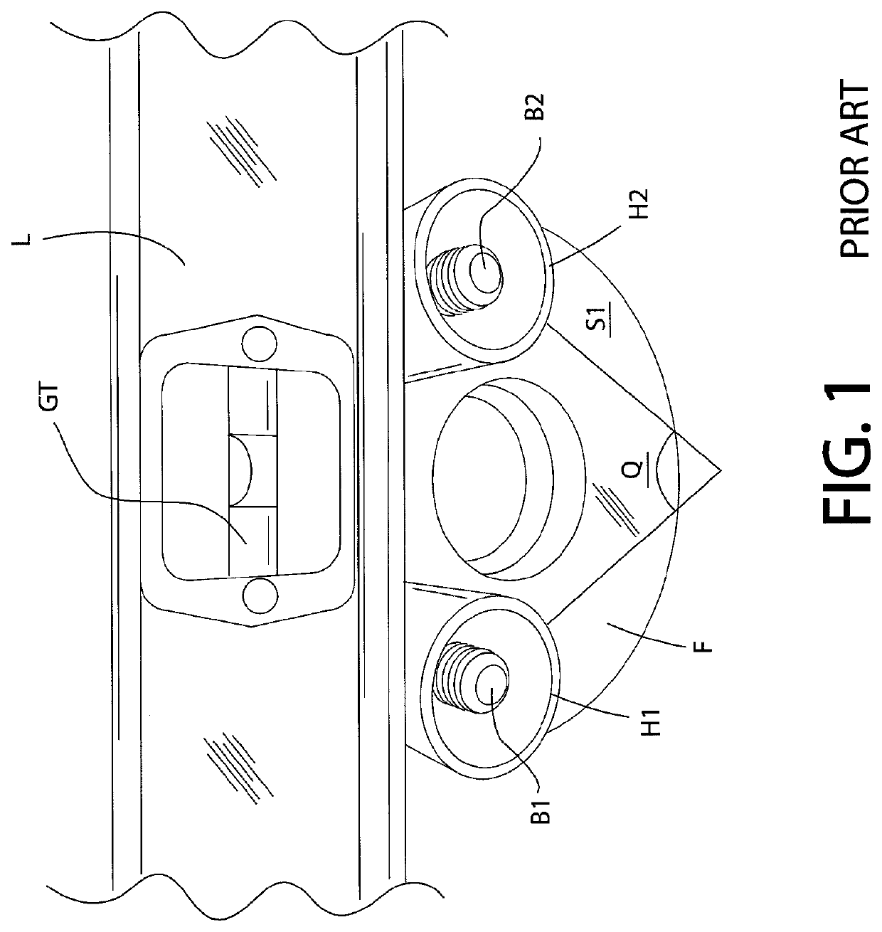
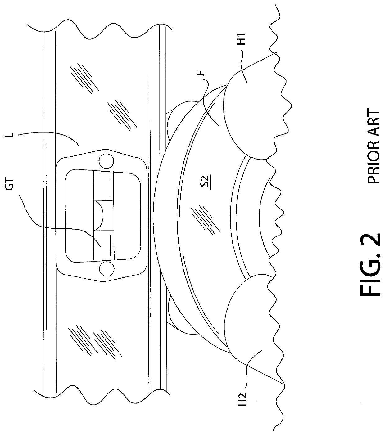
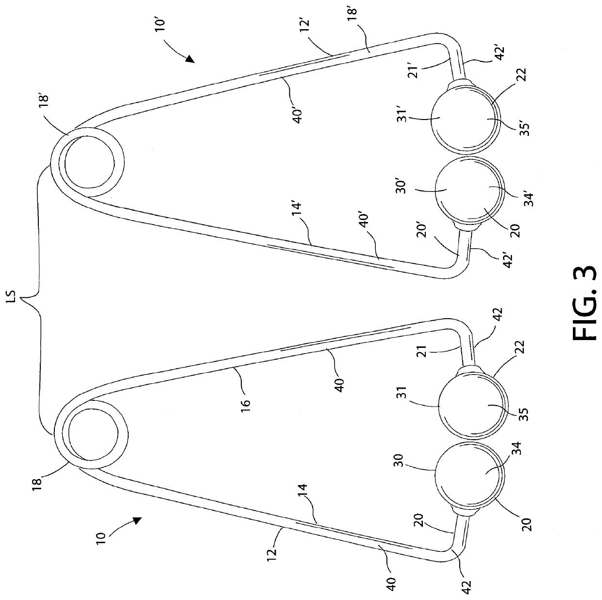
[0042]Embodiments of the invention generally relate to methods and a leveling system for supporting and aligning a flange relative to another object where the flange is to be secured. Some embodiments described herein relate to supporting and alignment of pipe flanges utilized in piping systems relative to pipe sections where the flange is to be secured. Embodiments of the leveling system include a flange support and alignment device that facilitates coaxial and / or concentric alignment of pipe flanges to the pipe sections. Embodiments of the invention may be utilized with pipe flanges including bolt-type flanges in the form of a plate or annular ring having a plurality of bolt holes formed in a pattern near an edge of the plate or ring. The bolt-type flanges include weld-neck flanges, raised face flanges, back-up flanges, blind flanges, slip-on flanges, la joint flanges, socket welding flanges, threaded flanges, and the like.

[0043]A flange leveling system of the prior art is illustr...


PUM


Abstract

A pipe flange is leveled for welding by using stainless steel using ball bearings attached to a U-shaped spring-loaded wire so a fitter is able to level a flange for welding while the wire supports a level. The ball bearings are part of a first leveling unit and a second leveling unit which comprise a flange leveling system. The spring acts to bias a first leg and a second leg of the leveling units such that the distal ends of both legs are biased toward each other. The ball bearings are axially co-linear with each other and are sized to be seated in bolt holes defined in the first and second sides of the pipe flange. A related process is also disclosed wherein the flange is adjusted until the associated flange holes on the first and second sides of the pipe flange are level with each other.

Description

CROSS REFERENCE TO RELATED APPLICATIONS[0001]This application claims priority to U.S. Provisional Patent Application Ser. No. 62 / 906,934 filed Sep. 27, 2019, the disclosure of which is incorporated herein by reference in its entirety.BACKGROUND OF THE INVENTION1. Field of the Invention[0002]The present invention relates, in general, to a flange leveling system and related methods for supporting and aligning a flange relative to a stationary object where the flange is to be secured. More specifically, embodiments of the invention generally relate to a method and a system for supporting and aligning a pipe flange relative to another flange or a tubular member, such as a joint of a pipe in the vicinity of the pipe flange which is to be fastened, such as, for example, by welding.2. Brief Description of the Prior Art[0003]A flange is a ring-like structure or a collar that is attached to a pipe for the purpose of providing support when two or more pipes are connected together either by we...

Claims


Application Information

Patent Timeline
Patent Type & Authority Applications(United States)
IPC IPC(8): F16L23/00G01C9/28B25B27/16
CPCF16L23/003B23K37/0536B25B27/16G01C9/28
Inventor TOOLEY, TRAVIS
Owner TOOLEY TRAVIS
Why Eureka
Try Eureka