Eureka AIR delivers breakthrough ideas for toughest innovation challenges, trusted by R&D personnel around the world.

Capturing apparatus

Pending Publication Date: 2022-02-03
PANASONIC INTELLECTUAL PROPERTY MANAGEMENT CO LTD
View PDF1 Cites 0 Cited by
  • Summary
  • Abstract
  • Description
  • Claims
  • Application Information

AI Technical Summary

Benefits of technology

The patent text describes the benefits of an invention. The invention has various advantages and can be implemented as a system, apparatus, method, integrated circuit, computer program, or recording medium. The technical effects of the invention can be found in the features described in the embodiment and specification.

Problems solved by technology

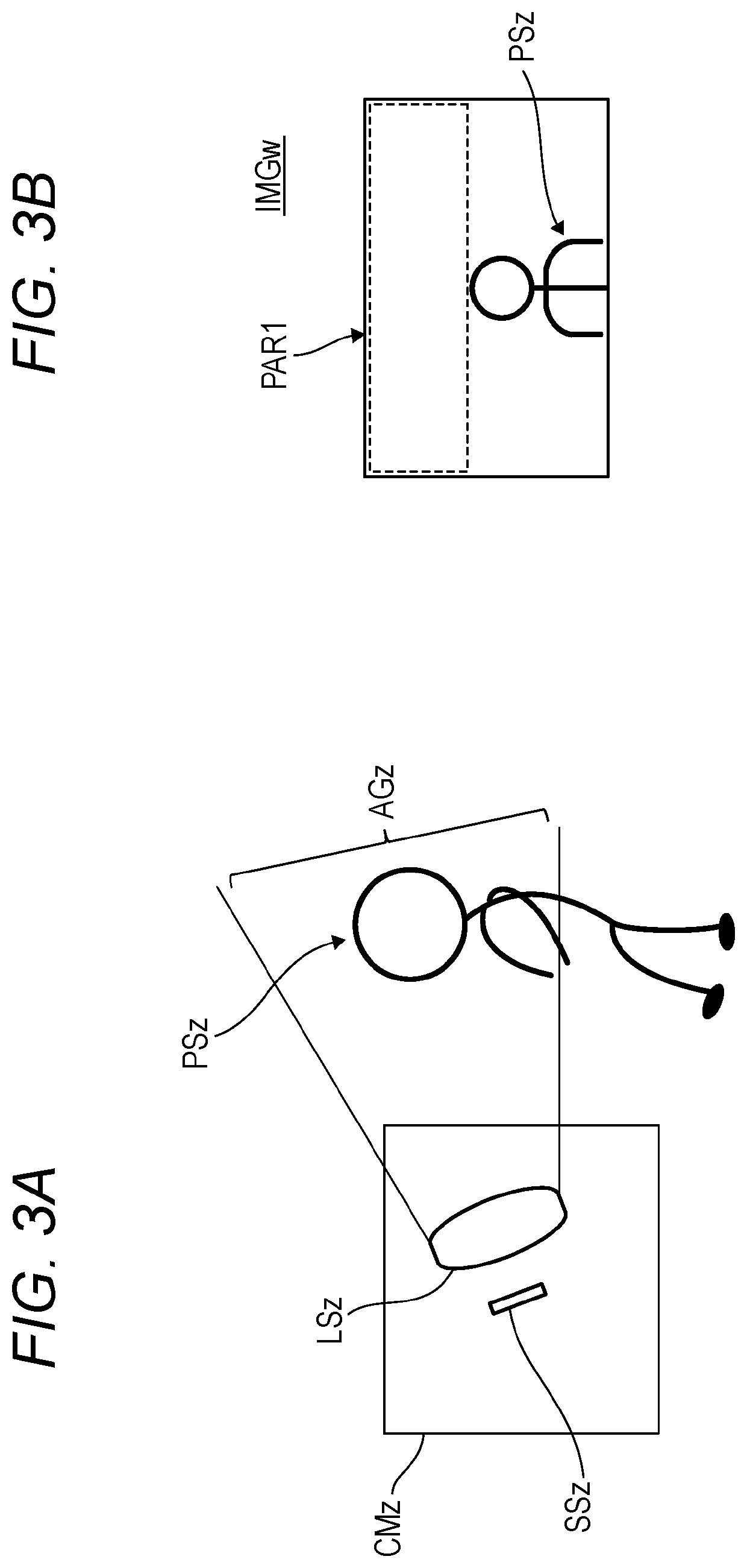
However, in a real environment, an installation position of the capturing apparatus and an angle of view for capturing of the capturing apparatus are restricted.
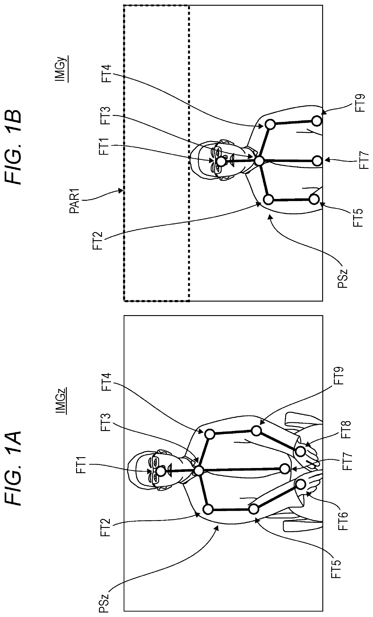
That is, the image shown in FIG. 1B has an unnecessary image region PAR1 and hence the angle of view of the camera is insufficient for capturing of a lower portion of the person PSz, resulting in a failure of detecting important skeletal points (e.g., located around his fingers) of the person PSz.
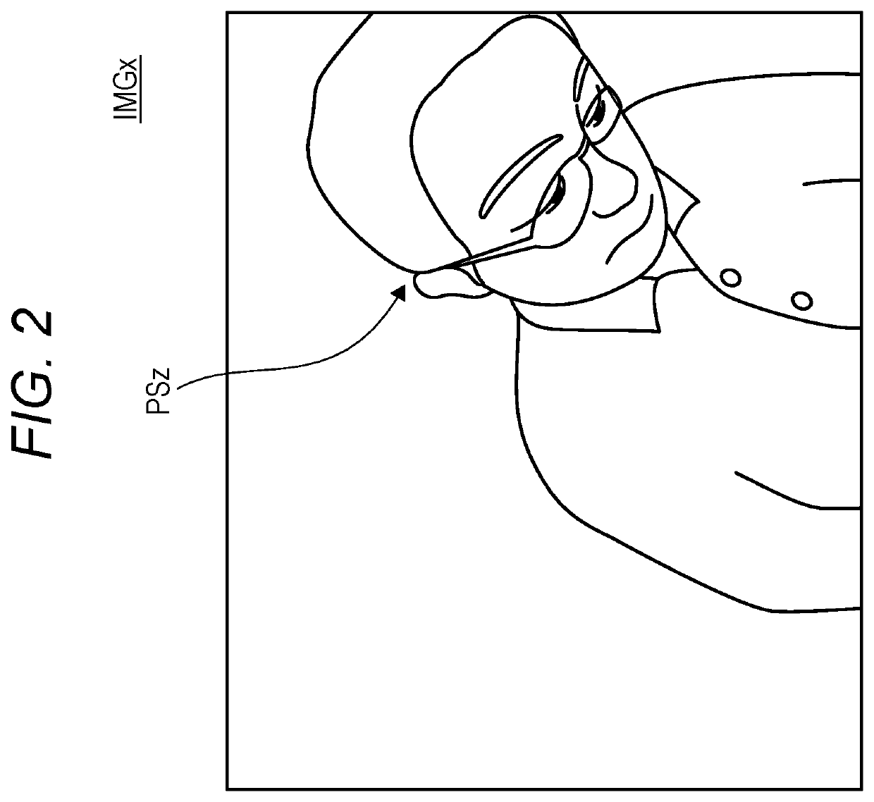
Thus, if the angle of view of the camera is insufficient for capturing of a lower portion of the person PSz, an image like an image IMGx shown in FIG. 2 is obtained and hence a movement of the hands of the pilot cannot be recognized.
As a result, for example, a posture of the pilot who bends forward to manipulate an instrument or write a current situation etc. on a notebook cannot be detected properly, possibly causing an event that he is judged unconscious erroneously (see FIG. 2).
However, it is difficult to for light coming from the hands or feet to enter on the capturing apparatus CM1 being interrupted by part of the instrument box ITM1.

Method used


Image

  • Capturing apparatus
  • Capturing apparatus
  • Capturing apparatus

Examples


embodiment 1

[0027]The first embodiment is directed to an example use in which a capturing apparatus CM1 according to the disclosure is installed in a cockpit CKP1 of an airplane and the object is a pilot of the airplane. However, uses of the first embodiment are not limited to this. For example, the capturing apparatus may be used in such a manner that it is installed in a body of the back of a seat of an airplane and the object is a passenger of the airplane.

[0028]FIG. 4 is a schematic diagram showing an example manner of disposition of the capturing apparatus CM1 according to the first embodiment. As shown in FIG. 4, for example, the capturing apparatus CM1 is installed in an instrument box ITM1 that is disposed in front of a person PS1 who is a pilot sitting in a pilot seat in a cockpit CKP1 of an airplane. For example, an installation space SP1 for the capturing apparatus CM1 is provided between some instruments and instruments adjacent them among the plural instruments installed in the ins...


PUM


Abstract

A capturing apparatus includes a capturing unit which captures an object, and a mirror which is installed in an angle of view of the capturing unit so as to exist as a part of an image captured by the capturing unit. The mirror reflects light coming from a part, existing outside the angle of view of the capturing unit, of the object so that the light enters on the capturing unit.

Description

BACKGROUND OF THE INVENTION1. Field of the Invention[0001]The present disclosure relates to a capturing apparatus.2. Background Art[0002]A passers-by watching system is known that watches for a nonpermitted person who is going to enter an entrance-restricted area illegally by eliminating blind spots of a surveillance camera instead of using plural surveillance cameras (refer to JP-A-2008-182459, for example). In this passers-by watching system, a camera capable of taking a moving image is installed on a wall portion located above a door. The camera captures the doorway and its neighborhood from a first direction. A mirror is fixed to a prescribed ceiling portion at a prescribed angle so as to be included in a capturing angle of view of the camera. When viewed from the installation position of the camera, a scene in the vicinity of the doorway as viewed from a second direction is reflected in the mirror. Whether one person or plural persons are passing through the doorway is judged b...

Claims


Application Information

Patent Timeline
IPC IPC(8): G06K9/00G06K9/46H04N5/265H04N5/225
CPCG06K9/00369H04N5/2253H04N5/265G06K9/4604H04N5/2621G06V10/147G06V10/16G06V40/103G06V10/145H04N23/55H04N23/80G06V10/44H04N23/54
Inventor ORIKASA, KEIICHIRO
Owner PANASONIC INTELLECTUAL PROPERTY MANAGEMENT CO LTD
Why Eureka
Eureka Blog
Learn More