Transport of container handling vehicles between storage grids of different heights

a container and transportation technology, applied in the field of automatica storage facility, can solve the problems of affecting the operation of the automated storage and retrieval system, and affecting the safety of the container handling vehicl

Pending Publication Date: 2022-02-10
AUTOSTORE TECH AS
View PDF0 Cites 7 Cited by
  • Summary
  • Abstract
  • Description
  • Claims
  • Application Information

AI Technical Summary

Benefits of technology

[0080]wherein the third horizontal plane (P3) is vertically displaced relative the first horizontal plane (P1) of the first track system and / or second horizontal plane (P2) of the second track system. The lift mechanism is arranged to move the platform between the first lift stop position, the second lift stop position and a third lift stop position, and in the third lift stop position establishing access between the platform and the third track system for enabling relocation of the vehicle between a support position on the platform and an operative position on the third track system.

Problems solved by technology

A problem associated with known automated storage and retrieval systems 1 is that the area surrounding the ports 19,20 may become congested with container handling vehicles 101 instructed to drop off or pick up storage containers 106.
This may seriously impede the operation of the automated storage and retrieval system 1.
This requires space, which may not necessarily be available.
Also, adding conveyor system infrastructure is costly.
Since the number of storage containers stored in a grid generally scales as the volume of the grid, but the space available for ports generally scales as the surface of the grid, increasing the number of ports will not necessarily solve the congestion problem when the grid size increases.
Another problem related to prior art automated storage and retrieval systems is the utilization of storage facilities such as a warehouse for housing the automated storage and retrieval systems.
As mentioned, the demand for larger sized automated storage and retrieval systems is increasing; a demand that may be challenged by the specific volumetric layout of certain warehouses when orienting the automated storage and retrieval systems in a suitable position to optimize the available storage space.
The provision and working of the automated storage and retrieval systems limits the actual outlays and options when fitting the systems into the storage facility.
However, not all storing facilities display an efficient cubic or rectangular storage space.
Consequently, some of the smaller spaces may be left vacant and thus valuable storage space is wasted.

Method used


Image

  • Transport of container handling vehicles between storage grids of different heights
  • Transport of container handling vehicles between storage grids of different heights
  • Transport of container handling vehicles between storage grids of different heights

Examples


Embodiment Construction

[0112]In the following, embodiments of the invention will be discussed in more detail with reference to the appended drawings. It should be understood, however, that the drawings are not intended to limit the invention to the subject-matter depicted in the drawings.

[0113]Particular embodiments of a storage structure of an automated storage and retrieval system 1 are shown in FIGS. 7-20.

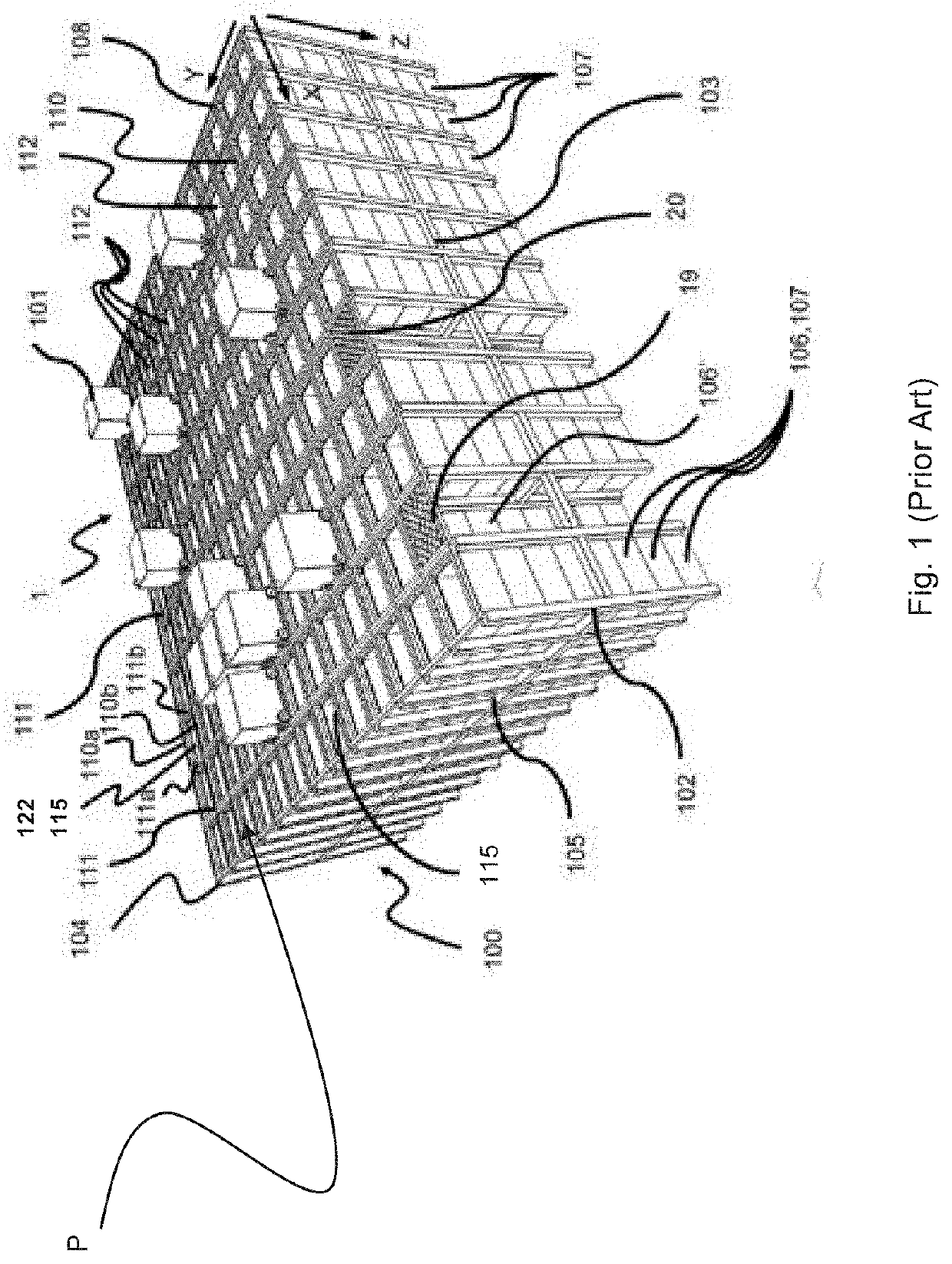
[0114]FIG. 1 shows the storage grid 104 of each storage structure which constitutes a framework 100 which may for example comprise a total of 1800 grid columns 112, where the width and length of the framework corresponds to the width and length of 36 and 50 grid columns 112, respectively. The top layer of the framework 100 is a track system 108 onto which a plurality of vehicles 3,101 are operated.

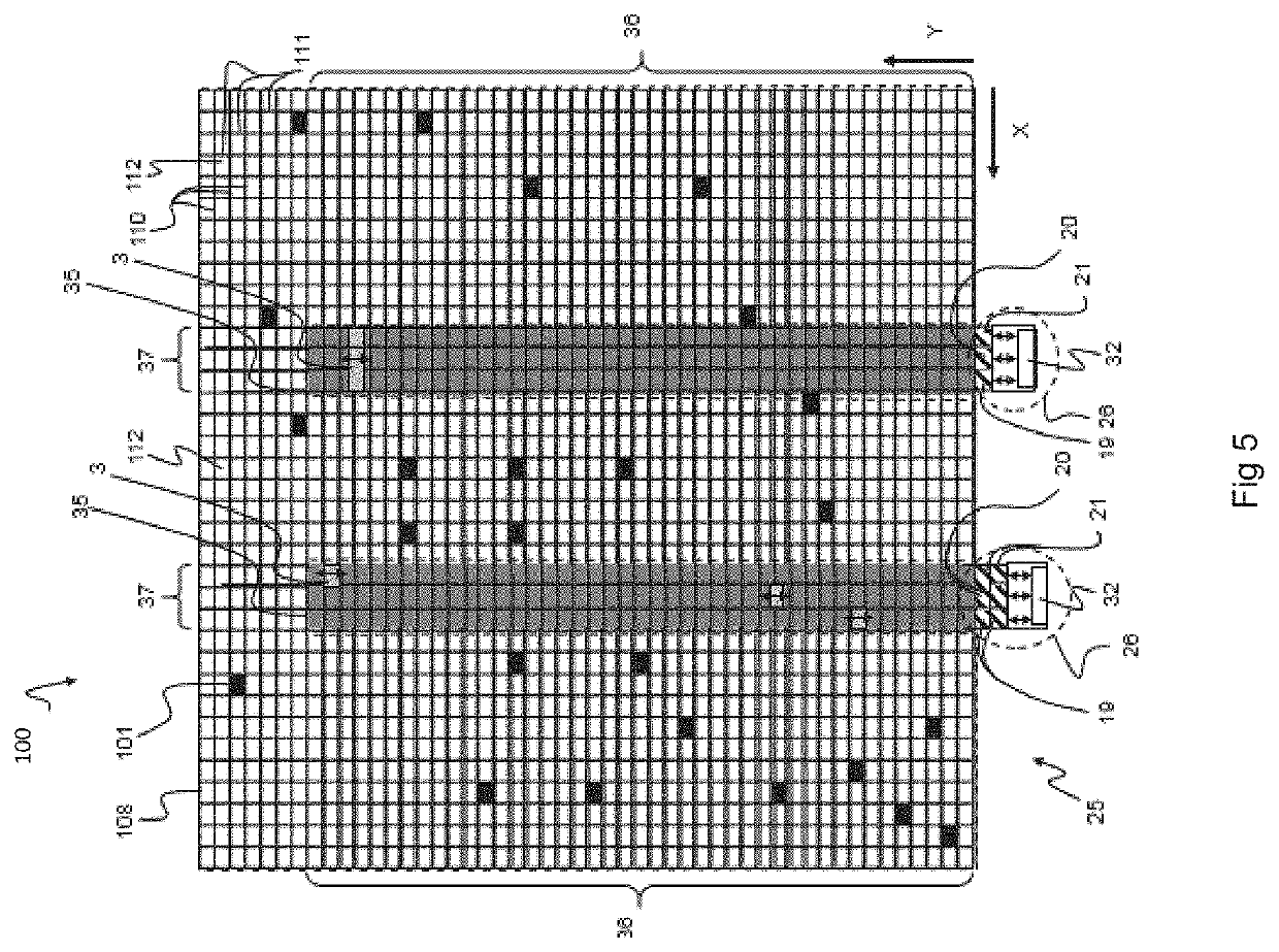
[0115]FIG. 5 shows two types of vehicles 3,101, indicated by black and light grey rectangles. The black rectangles symbolize exemplary positions of container handling vehicles 101 intended to transport stora...


PUM


Abstract

An automated storage and retrieval system includes a first track system and a second track system. The first track system includes a first set of parallel tracks arranged in a first horizontal plane and extending in a first direction of the first track system and a second set of parallel tracks arranged in the first horizontal plane and extending in a second direction of the first track system which is orthogonal to the first direction of the first track system. The first and second sets of tracks of the first track system forming a grid pattern in the first horizontal plane including a plurality of adjacent grid cells. Each grid cell of the first track system comprising a grid opening defined by a pair of neighboring tracks of the first set of tracks and a pair of neighboring tracks of the second set of tracks. Storage columns are located beneath the first track system for storing storage containers in a plurality of stacks. Each storage column is located vertically below a grid opening. The second track system includes a third set of parallel tracks arranged in a second horizontal plane and extending in a first direction of the second track system, and a fourth set of parallel tracks arranged in the second horizontal plane and extending in a second direction of the second track system which is orthogonal to the first direction of the second track system. The third and fourth sets of tracks forming a grid pattern in the second horizontal plane including a plurality of adjacent grid cells. Each grid cell of the second track system including a grid opening defined by a pair of neighboring tracks of the third set of tracks and a pair of neighboring tracks of the fourth set of tracks. Storage columns are located beneath the second track system for storing storage containers in a plurality of stacks. Each storage column is located vertically below a grid opening. The first horizontal plane of the first track system and second horizontal plane of the second track system are arranged vertically displaced relative each other. The automated storage and retrieval system further includes a vehicle lift device for transfer of at least one vehicle arranged on the first track system to the second transfer system and vice versa. The vehicle lift device includes a platform arranged to carry the vehicle and a lift mechanism arranged to move the platform between: a first lift stop position establishing access between the platform and the first track system for enabling relocation of the vehicle between a support position on the platform and an operative position on the first track system, and a second lift stop position establishing access between the platform and the second track system for enabling relocation of the vehicle between the support position on the platform and an operative position on the second track system.

Description

TECHNICAL FIELD[0001]The present invention relates to an automated storage and retrieval system, a storage facility and a method thereof.BACKGROUND AND PRIOR ART[0002]FIG. 1 discloses a typical prior art automated storage and retrieval system 1 with a framework structure 100 and FIG. 2A and B disclose a prior art container handling vehicle 101 of such a system 1.[0003]The framework structure 100 comprises a plurality of upright members 102 and a plurality of horizontal members 103 which are supported by the upright members 102. The members 102, 103 may typically be made of metal, e.g. extruded aluminum profiles.[0004]The framework structure 100 defines a storage grid 104 comprising storage columns 105 arranged in rows, in which storage columns 105 storage containers 106, also known as bins, are stacked one on top of another to form stacks 107. Each storage container 106 may typically hold a plurality of product items (not shown), and the product items within a storage container 106 ...

Claims


Application Information

Patent Timeline
Patent Type & Authority Applications(United States)
IPC IPC(8): B65G1/04B66B9/00B61B5/02
CPCB65G1/0464B61B5/02B66B9/00B65G1/04
Inventor AUSTRHEIM, TROND
Owner AUTOSTORE TECH AS
Why Eureka
Try Eureka