Apparatus and method for the automated management of bacterial load detector devices

a technology of bacterial load detector and automatic management, applied in the direction of manipulators, material analysis, manufacturing tools, etc., can solve the problems of operator safety problems, incisions on gloves, toxic and/or harmful to their health, etc., to eliminate or increase the safety of operators, simple and quick and reliable manner

Pending Publication Date: 2022-02-24
IMA IND MASCH AUTOMATICHE SPA
View PDF0 Cites 0 Cited by
  • Summary
  • Abstract
  • Description
  • Claims
  • Application Information

AI Technical Summary

Benefits of technology

[0042]The shape and the disposition of the sliding and guide means and of the respective guide members are such that the slider completes a fixed and defined path both during the insertion into the chamber, and also during its removal therefrom to be placed back in the transfer device at the end of the collection of the plates. This allows to move the housing slider in a simple, quick and reliable manner, allowing this operation to be perfo

Problems solved by technology

One disadvantage of these known solutions is that the gloves used, while allowing to operate inside the insulator in a manner that is separate from it, can be a mean of conveying contaminants inside the chamber.
In fact, it can happen that during use, holes or incisions form on the gloves, through which contaminants can penetrate inside the protected chamber.
Furthermore, these solutions can lead to safety problems for operators, for example in the case where gloves are damaged and the operators come into contact with pharmaceutical products which can be dangerous, toxic and/or harmful to their health, or harmful to the surrounding environment.
In the known solutions, moreover, the gloves can lead to contamination of the plates during their insertion into and/or during their removal from the chamber, or during the step of closing the plates, thus compromising the correct monitoring of the sterility of the internal environment of the chamber.
The subsequent analysis, in fac

Method used


Image

  • Apparatus and method for the automated management of bacterial load detector devices
  • Apparatus and method for the automated management of bacterial load detector devices
  • Apparatus and method for the automated management of bacterial load detector devices

Examples


Embodiment Construction

[0060]We will now refer in detail to the various embodiments of the present invention, of which one or more examples are shown in the attached drawings. Each example is supplied by way of illustration of the invention and shall not be understood as a limitation thereof. For example, the characteristics shown or described insomuch as they are part of one embodiment can be adopted on, or in association with, other embodiments to produce another embodiment. It is understood that the present invention shall include all such modifications and variants.

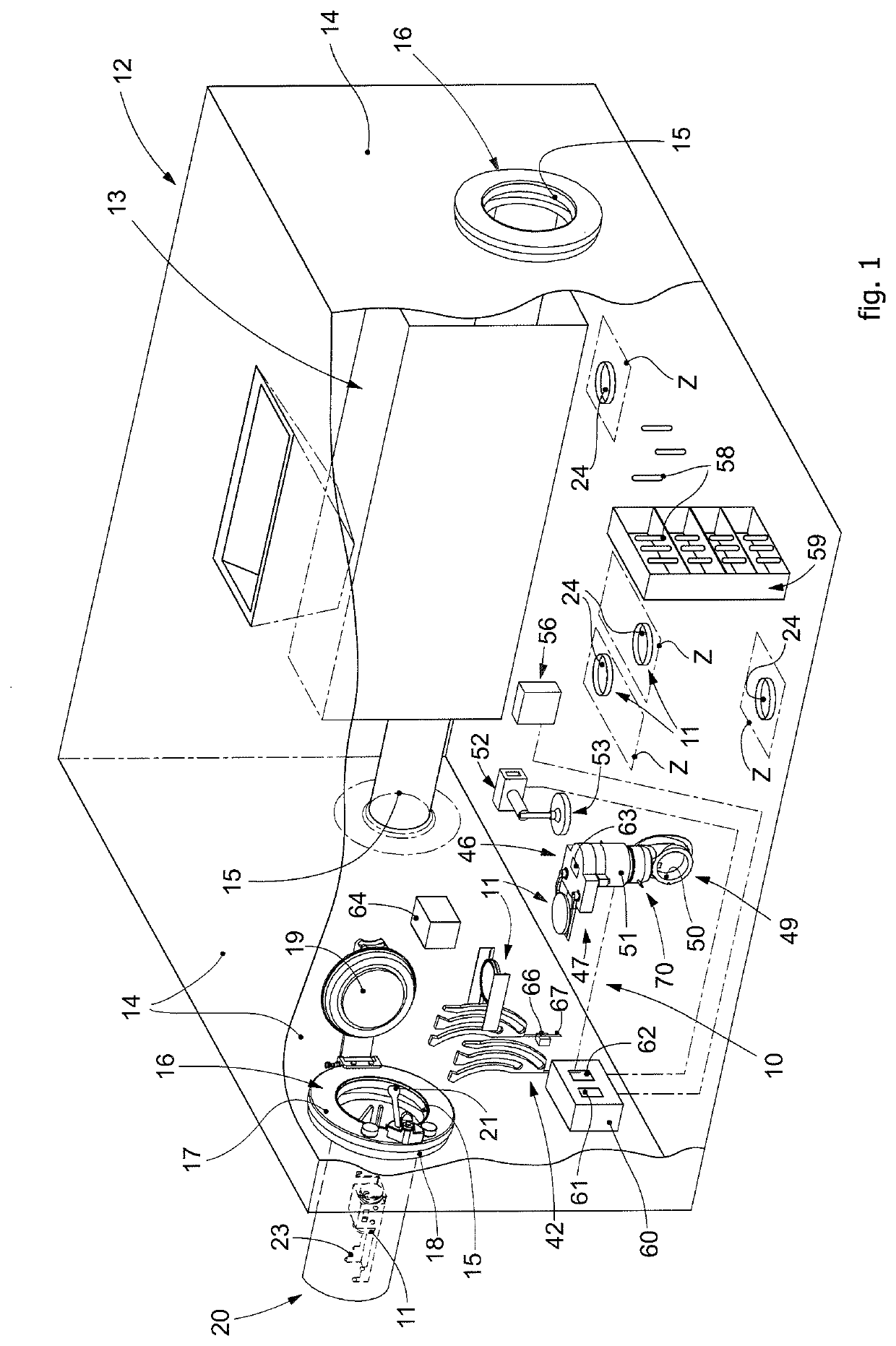
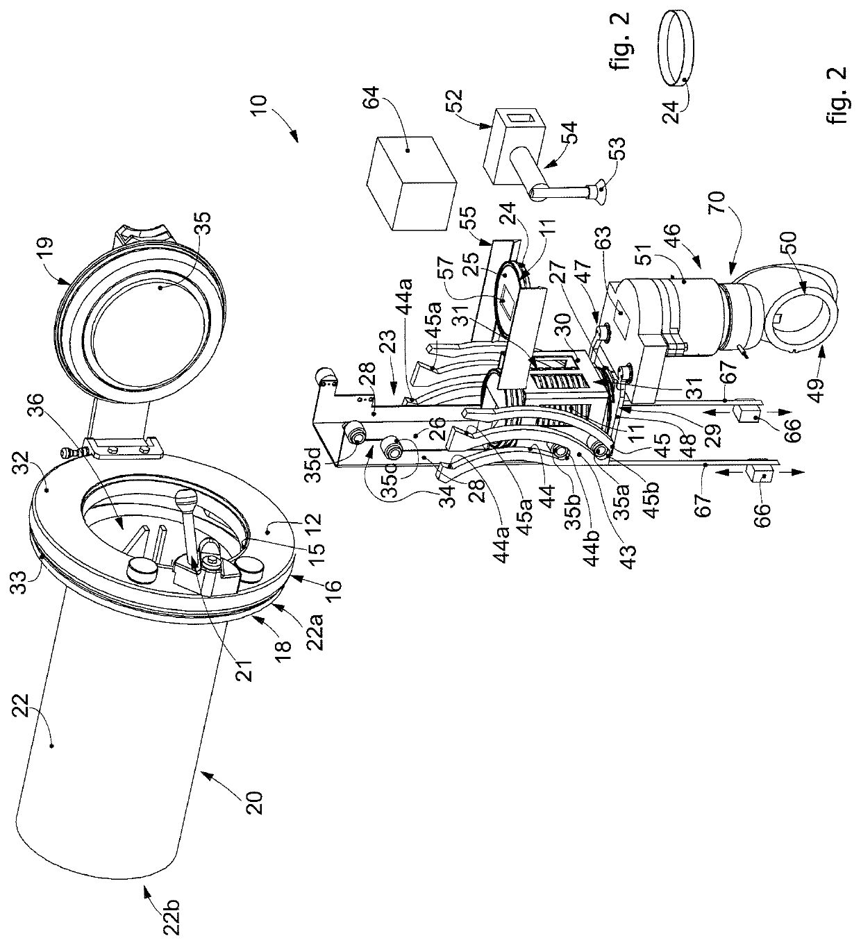
[0061]Embodiments described here concern an apparatus 10 for the automated management of bacterial load detector devices inside a protected chamber 12 or clean room, also called “isolator” in the field, of a machine for processing and / or packaging pharmaceutical products.

[0062]Here and in the following description, we will describe, by way of a non-limiting example, embodiments in which the bacterial load detector devices are configured as ...


PUM


Abstract

An apparatus and method are described for the automated management of bacterial load detector devices to be temporarily positioned inside a clean room, delimited by walls, at least one of which is provided with at least one access aperture on which a primary closing unit is installed, configured to allow access to the inside of the chamber while keeping its atmosphere isolated and separated from the external environment. The apparatus includes a transport container, containing inside it an extractable housing slider on which one or more bacterial load detector devices are positioned, an extraction device configured to extract the slider from the transport container and make it available inside the chamber, and a support device disposed inside the chamber configured to stably position and support the slider.

Description

FIELD OF THE INVENTION[0001]The invention concerns an apparatus and method for the automated management of bacterial load detector devices, such as for example sedimentation plates, in particular Petri dishes, or swabs. The apparatus according to the present invention is configured, in particular, to automatically insert and remove the devices as above inside a machine for packaging or processing pharmaceutical products that operates in a protected environment and in controlled and defined atmospheric conditions, generally called “isolator”.BACKGROUND OF THE INVENTION[0002]In the pharmaceutical sector, the operations of processing and packaging pharmaceutical products such as, for example, powders, tablets, pills, or suchlike, are carried out inside a chamber protected and separated from the external environment, generally called “clean room” or “isolator”, which is kept in sterile conditions and at a controlled atmosphere.[0003]Processing and / or packaging devices and equipment are ...

Claims


Application Information

Patent Timeline
IPC IPC(8): B25J21/00G01N35/04
CPCB25J21/005G01N2035/0465G01N2035/0429G01N35/04B25J5/00
Inventor GABUSI, GABRIELE
Owner IMA IND MASCH AUTOMATICHE SPA
Why Eureka
Try Eureka