Aircraft rib-spar joint

a technology of ribspar joints and ribs, which is applied in the direction of measuring/indicating equipment, wings, transportation and packaging, etc., can solve the problems of large amount of tooling, subject to operator errors, and time-consuming assembly process, and achieve the effect of improving operator safety

Active Publication Date: 2012-03-29
AIRBUS OPERATIONS LTD
View PDF2 Cites 1 Cited by
  • Summary
  • Abstract
  • Description
  • Claims
  • Application Information

AI Technical Summary

Benefits of technology

[0021]The aircraft wing may be assembled with the rib longitudinal axis being substantially horizontal (i.e. level flight orientation). A horizontal orientation may improve operator safety and enable assembly in height restricted buildings. However, the invention may also be applicable to a wing assembly in a vertical orientation (i.e. rib longitudinal axis being substantially vertical).

Problems solved by technology

As it was a manual process, it was subject to operator error.
The assembly process was time consuming often requiring several checking and adjusting cycles to achieve the optimum position.
Each rib required a set of eight unique gauges, resulting in a large amount of tooling.
In addition, with the move from traditional metallic to composite materials, e.g. carbon fibre reinforced plastic (CFRP), for at least some of the wing box structural components, the tolerances have increased adding more complexity and variation to the assembly process.
However, manual manipulation of the structural wing components during assembly is made more difficult with this horizontal orientation due to the influence of gravity.

Method used


Image

  • Aircraft rib-spar joint
  • Aircraft rib-spar joint
  • Aircraft rib-spar joint

Examples


Embodiment Construction

)

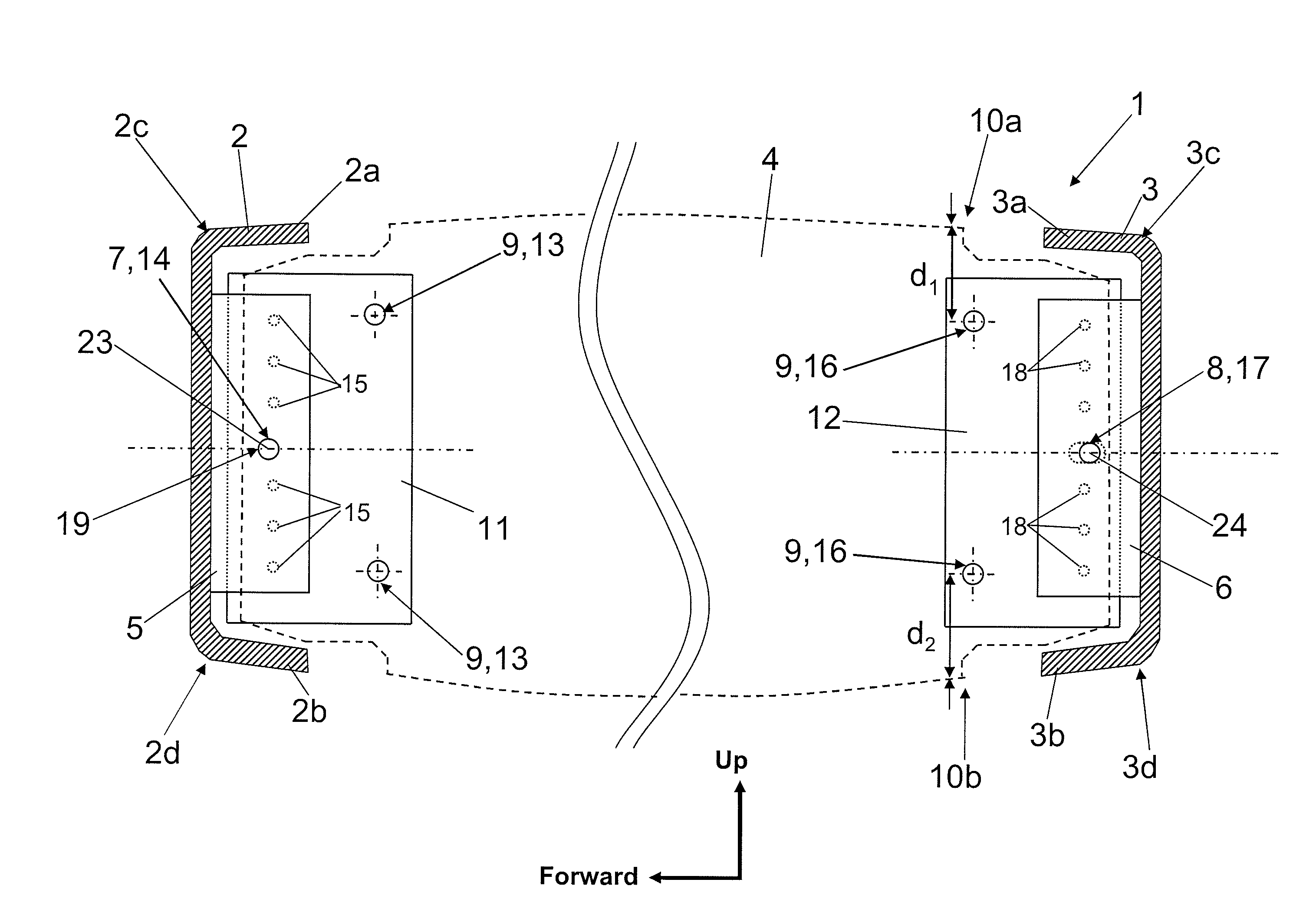
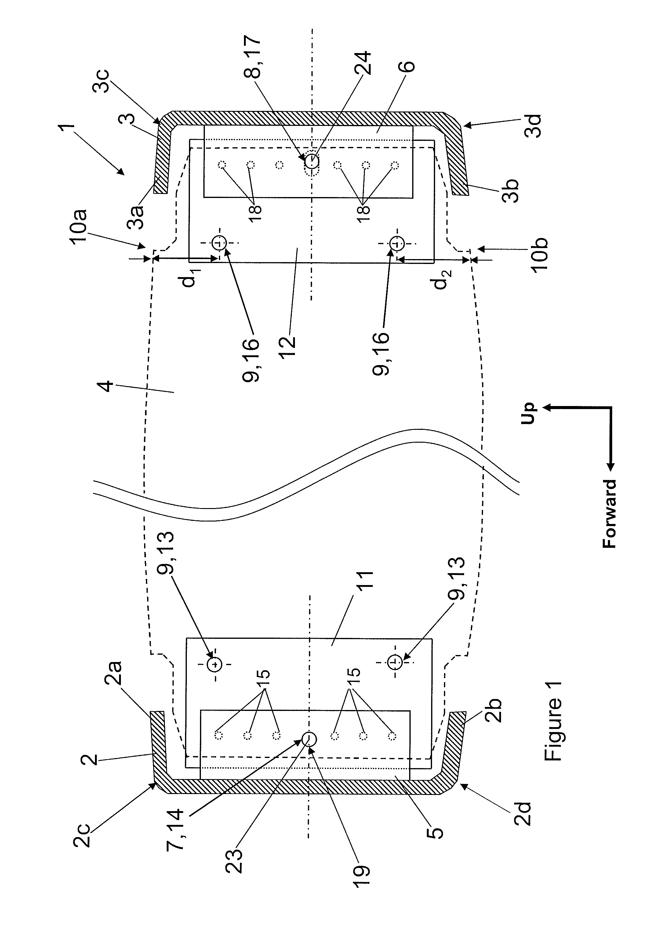
[0029]FIG. 1 illustrates a vertical section through an aircraft wing box 1 during assembly. The wing box includes a front spar 2 a rear spar 3 a plurality of ribs (the outline of one of the ribs 4 is shown in broken line in FIG. 1) extending between the spars 2, 3, and upper and lower wing covers, or skins (not shown), extending between the spars 2, 3. The front spar 2 has a rib post 5 fixedly attached thereto, and the rear spar 3 has a rib post 6 fixedly attached thereto. The wing box is assembled by attaching each of the plurality of ribs 4 to respective rib posts 5, 6 attached at spaced locations along the front and rear spars 2, 3. Subsequently, upper and lower wing covers (not shown) are attached to spar flanges 2a, 2b, 3a, 3b and to rib feet (not shown) of the ribs 4.

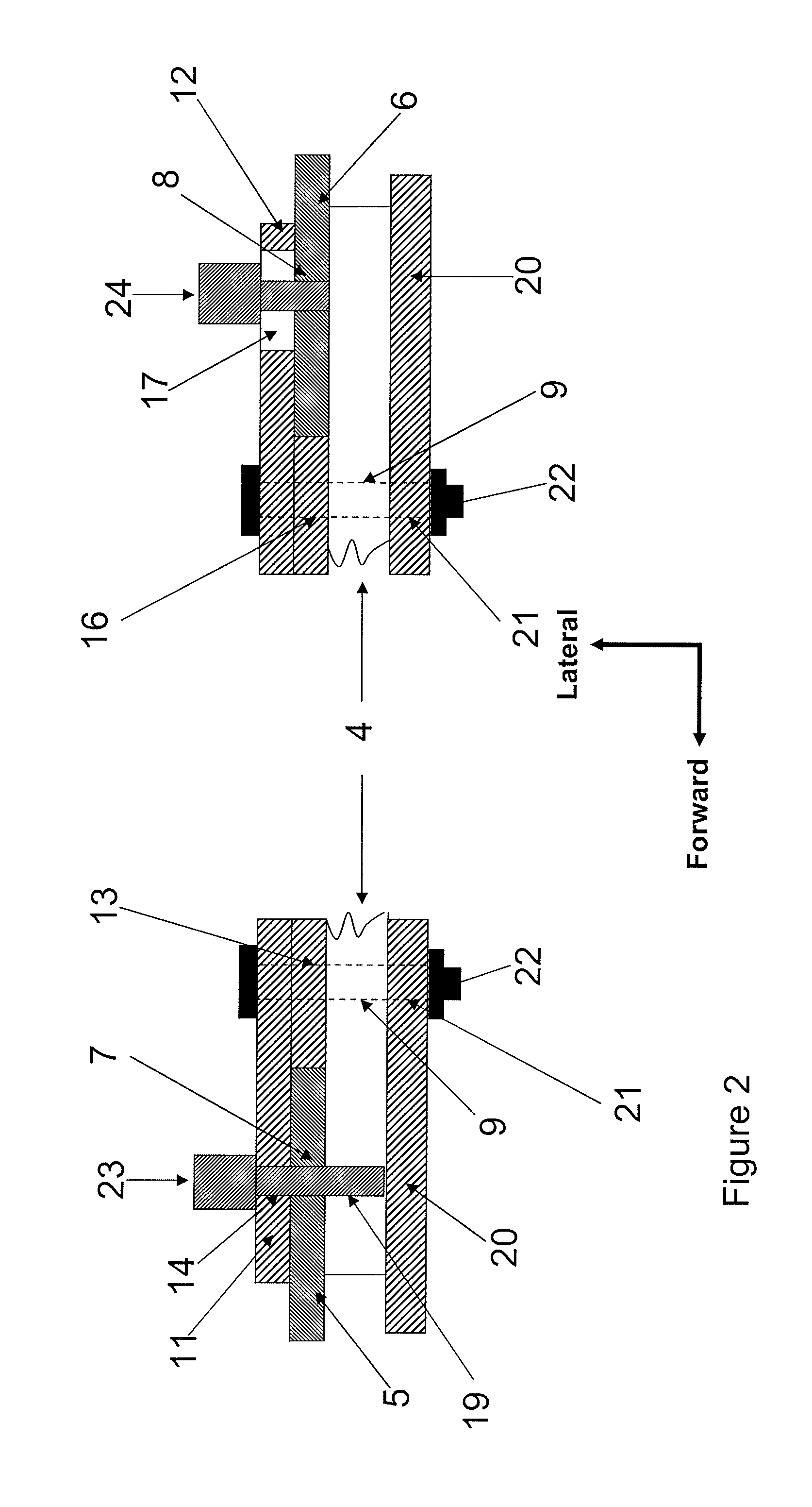
[0030]The attachment of the rib 4 to the rib posts 5, 6 will now be described in detail. The front and rear spars 2, 3 are fixed in predetermined positions relative to one another. This may be done using an appro...


PUM

PropertyMeasurementUnit
stress concentrationaaaaaaaaaa
gravityaaaaaaaaaa
timeaaaaaaaaaa

Abstract

A method of forming a rib-spar joint during assembly of an aircraft wing, the method comprising: providing a spar with a fixedly attached rib post, the rib post having a first coordination feature; providing a rib having a web with a first tooling feature; providing a tooling component having a second tooling feature for cooperating with the first tooling feature, a second coordination feature for cooperating with the first coordination feature, and a plurality of drill bushings; fixedly attaching the tooling component to the rib web by aligning the first and second tooling features; aligning the rib with the spar by aligning the first and second coordination features; drilling fastener holes in the rib and the rib post off the drill bushings of the tooling component; removing the tooling component from the rib web; and fastening the rib to the rib post using the fastener holes to form a rib-spar joint. The method may be applied to form front and/or rear rib-spar joints.

Description

FIELD OF THE INVENTION[0001]The present invention relates to a method of forming a rib-spar joint during assembly of an aircraft wing.BACKGROUND OF THE INVENTION[0002]Aircraft wings typically include front and rear spars, ribs extending between the spars, and upper and lower covers (skins) extending between the spars. The outer surfaces of the covers form part of the aerodynamic wing profile. The spars, ribs and covers are assembled to form a wing box structure.[0003]An existing method for forming rib-spar joints between the ribs and the spars during assembly of the wing includes manually installing the ribs and adjusting their position based on gap measurements taken with feeler gauges to the adjacent spar structure using tooling gauges placed at the four corners of each rib component. This method has several drawbacks. As it was a manual process, it was subject to operator error. The assembly process was time consuming often requiring several checking and adjusting cycles to achie...

Claims


Application Information

Patent Timeline
Patent Type & Authority Applications(United States)
IPC IPC(8): B21D53/92
CPCB64C3/187Y10T408/55Y10T29/49622Y10T29/53978Y10T29/4978B64F5/0009B64C3/185B64F5/10
Inventor BESTWICK, RICHARDGRANT, SCOTT
Owner AIRBUS OPERATIONS LTD
Why Eureka
Try Eureka