Automatic disconnection mechanism for switches

Inactive Publication Date: 2021-06-17
WANG GANG
View PDF0 Cites 0 Cited by
  • Summary
  • Abstract
  • Description
  • Claims
  • Application Information

AI Technical Summary

Benefits of technology

[0015]The automatic disconnection mechanism of the invention enables the inverter circuit system to remotely disconnect the inverter system circuit without manual operation when it encounters special conditions such as overload and short circuit, which avoids accidents such as b

Problems solved by technology

With the extensive construction of power systems in China, the safety of power systems has gradually become a concern of the general public and has become a hot issue in the industry in recent years.
However, the knob-type isolation switch currently used in the market is basically manually operated, and the operator needs to manually disconnect the switch after a fault is found, which undoubtedly increases the safet

Method used


Image

  • Automatic disconnection mechanism for switches
  • Automatic disconnection mechanism for switches
  • Automatic disconnection mechanism for switches

Examples


embodiment 1

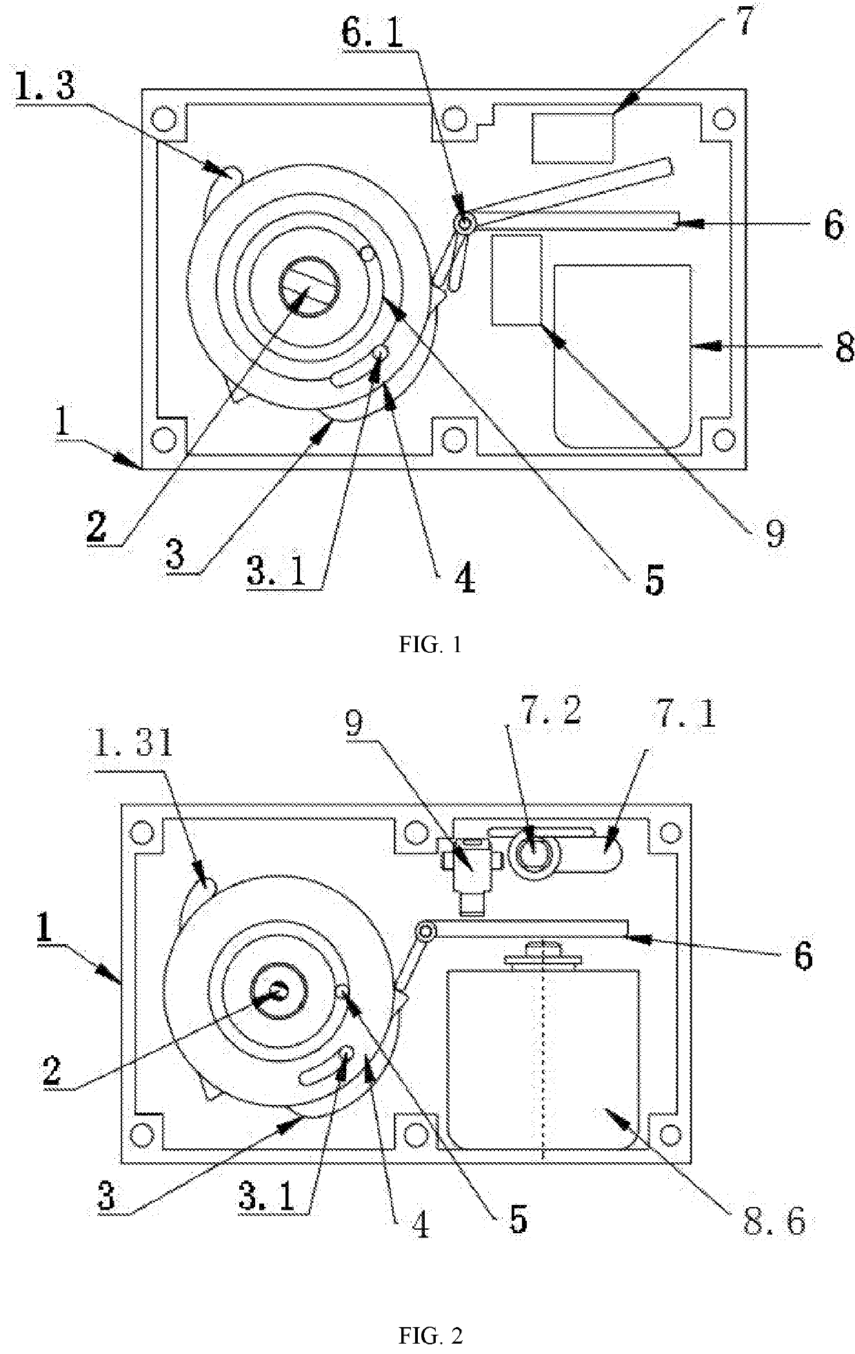
[0028]With reference to FIGS. 1, 2, and 6-9, an automatic disconnection mechanism for switches, comprising a shell 1, wherein the inside of the shell 1 is hollow, and the shell 1 is provided with a spindle 2, a cam 3 sleeved on the spindle 2, a rotary ratchet 4 sleeved on the spindle 2, a torsional spring 5 sleeved on the spindle 2, a control ratchet needle 6 that mates with the rotary ratchet 4, and a limiting mechanism 1.3 for limiting the rotation range of the cam 3; the spindle 2 penetrates the shell 1 and is integrated with the switch shaft; the cam 3 is fixedly connected to the spindle 2, and one end surface thereof is provided with a guide pin 3.1; the rotary ratchet 4 is disposed on a side of the cam 3 on which the guide pin 3.1 is provided and mates with the hole of the spindle 2; the torsional spring 5 is disposed on a side of the rotary ratchet 4 and enables the torsional spring 5 to be in a tightened state when the spindle 2 rotates clockwise with the switch shaft; the c...

embodiment 2

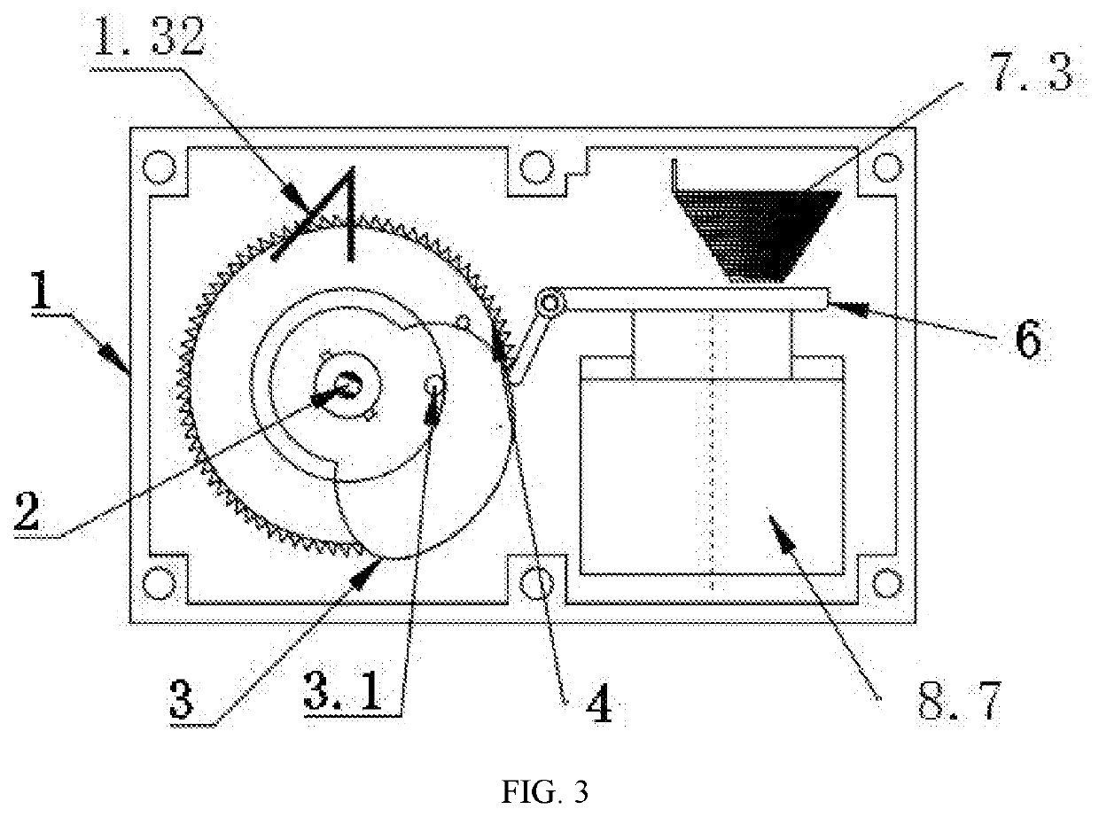
[0034]With reference to FIGS. 1, 3, and 7-9, compared with Embodiment 1, the Embodiment differs from Embodiment 1 in that:

[0035]the limiting mechanism 1.3 is a brake spring tab 1.31; one end of the torsional spring 5 is connected to the shell and the other end thereof is fixedly connected to the cam 3; the spindle 2 is fixedly connected to the pin of the rotary ratchet 4; the reset mechanism 7 is a reset spring 7.3; the trigger mechanism 8 is an impact electromagnet 8.7.

embodiment 3

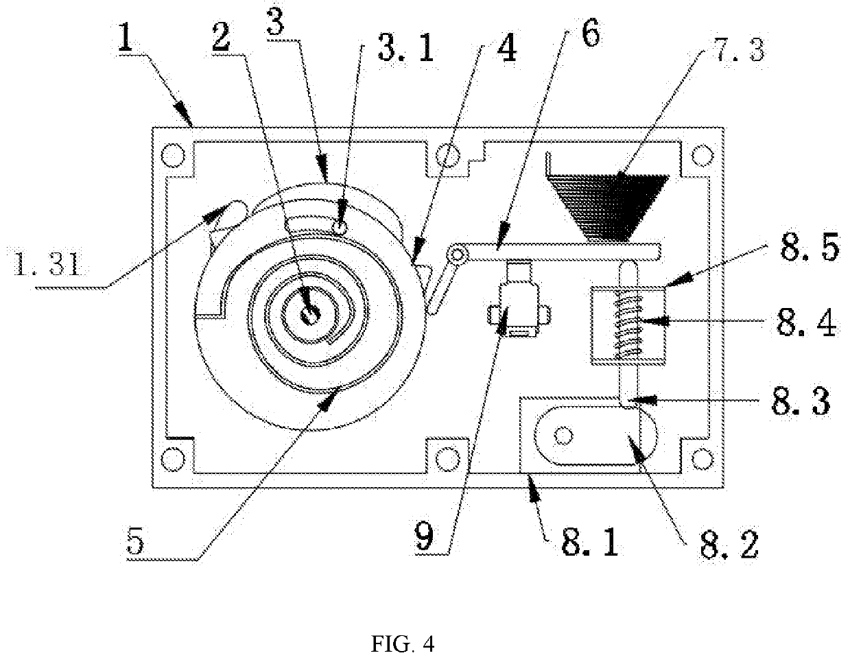
[0036]With reference to FIGS. 1, 4, and 7-9, compared with Embodiment 1, the Embodiment differs from Embodiment 1 in that:

[0037]the limiting mechanism 1.3 is a long elliptical bulge 1.31; the spindle 2 is connected to the gear of the rotary ratchet 4; one end of the torsional spring 5 is connected to the shell and the other end thereof is fixedly connected to the spindle 2; the reset mechanism 7 is a reset spring 7.3; the trigger mechanism 8 comprises a motor, 8.1 a trigger cam 8.2 connected to the motor 8.1, and a push rod 8.3 connected to the trigger cam 8.2; the outside of the push rod 8.3 is provided with a frame 8.5 for fixing the push rod 8.3, the frame 8.5 is fixedly connected to the shell 1, and the inside of the frame is provided with a trigger spring 8.4 sleeved on the push rod 8.3; the shell 1 is further provided with a microswitch 9, and the microswitch 9 is disposed on a side of the reset mechanism 8 close to the lock plate 6.3.


PUM


Abstract

The invention discloses an automatic disconnection mechanism for switches, comprising a shell, wherein the inside of the shell is hollow, and the shell is provided with a spindle, a cam sleeved on the spindle, a rotary ratchet sleeved on the spindle, a torsional spring sleeved on the spindle, a control ratchet needle that mates with the rotary ratchet, and a limiting mechanism for limiting the rotation range of the cam. The automatic disconnection mechanism of the invention enables the inverter circuit system to remotely disconnect the inverter system circuit without manual operation when it encounters special conditions such as overload and short circuit, which avoids accidents such as burnout of the inverter caused by circuit overload and short circuit and improves the safety of the operator. The automatic disconnection mechanism of the invention and the photovoltaic switch are installed together as an automatic disconnection system for the photovoltaic switch.

Description

BACKGROUND OF THE INVENTION1. Field of the Invention[0001]The invention relates to the technical field of circuit protection, in particular to an automatic disconnection mechanism for switches.2. Description of the Related Art[0002]With the extensive construction of power systems in China, the safety of power systems has gradually become a concern of the general public and has become a hot issue in the industry in recent years. In particular, DC switches are used in inverters to control the working states of multiple core components. The reliability of DC switches is not only related to the good operation of the entire power system, but also to the stable development of the power industry.[0003]Looking back on the development of the photovoltaic industry in the past few years, the industry has gradually established standards for the use of photovoltaic switches. Major manufacturers have also been researching to enhance the ability of arc extinction for switch contacts and the speed ...

Claims


Application Information

Patent Timeline
IPC IPC(8): H01H9/20
CPCH01H9/20H01H2300/018H01H33/02H01H33/28H01H3/30H01H3/3031H01H3/3042H01H33/40
Inventor WANG, GANG
Owner WANG GANG
Why Eureka
Try Eureka