Method of measuring true shear viscosity profile of molding material in capillary and molding system performing the same

Active Publication Date: 2022-03-03
CORETECH SYST
View PDF0 Cites 0 Cited by
  • Summary
  • Abstract
  • Description
  • Claims
  • Application Information

AI Technical Summary

Benefits of technology

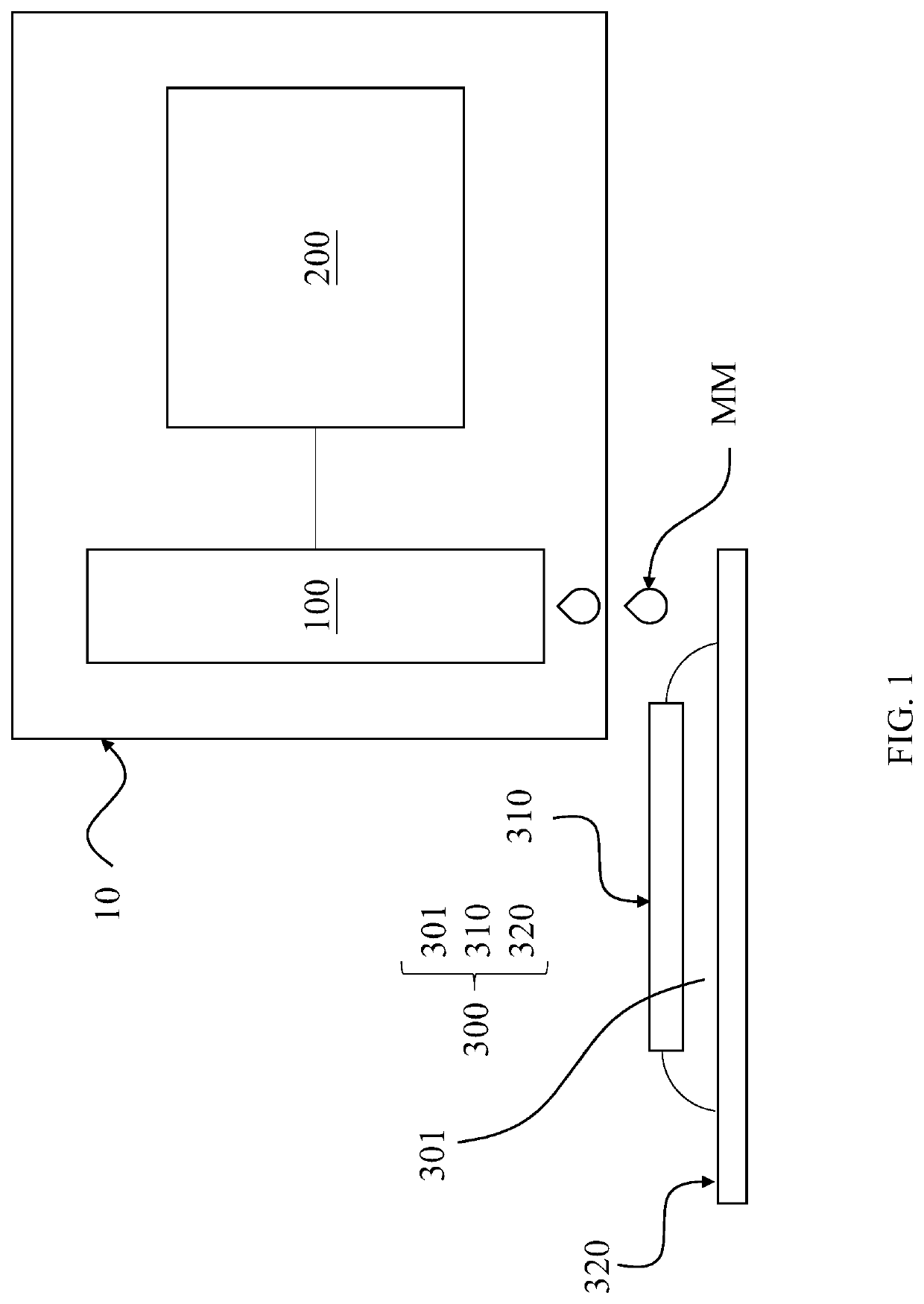
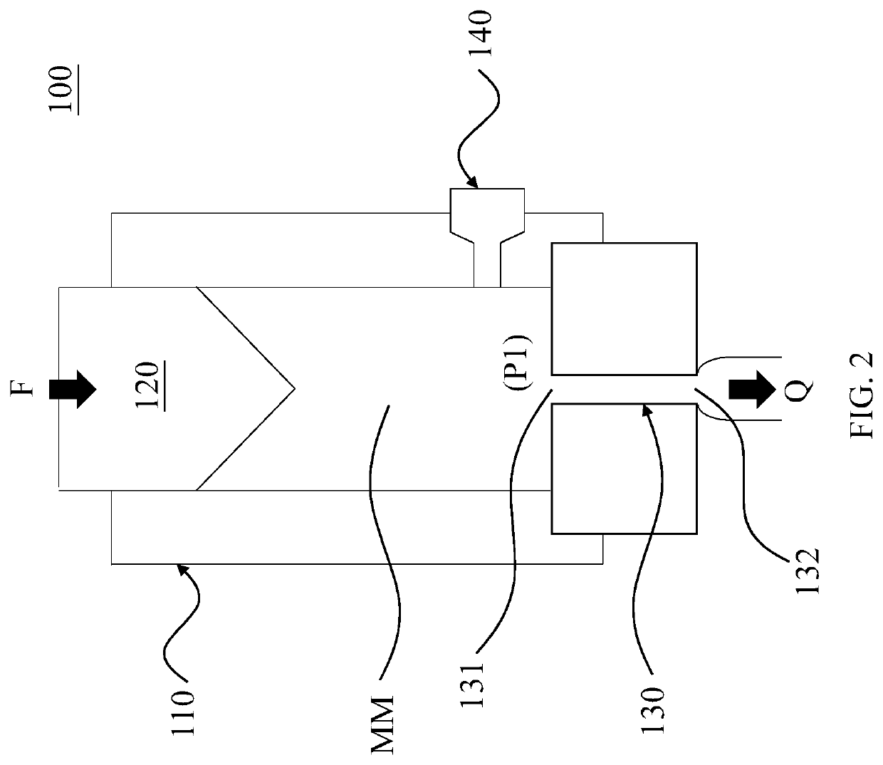
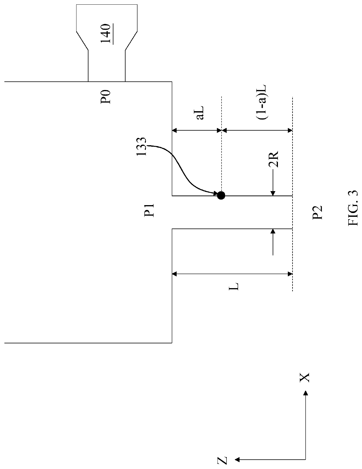
The present patent provides a method for measuring the true shear viscosity profile of a molding material in a capillary, which involves determining the initial temperature profile of the molding material at the setpoint temperature with respect to the shear rate, and fitting the initial shear viscosity profile with the temperature profile to obtain the true shear viscosity profile. The method can be used in a molding system that includes a dispenser and a rheometer. The technical effect of the patent is to provide a more accurate measure of the viscosity profile of a molding material in a capillary, which can improve the quality and efficiency of the molding process.

Problems solved by technology

However, these assumptions are inappropriate in some situations.
For example, when the molding material has a temperature change, the flow behavior of the molding material will be simulated inaccurately.
Consequently, the result of the injection molding will deviate from the simulation which makes the injection molding process inefficient.
Therefore, the accuracy of the simulation of the molding material has become a critical issue in this field.

Method used


Image

  • Method of measuring true shear viscosity profile of molding material in capillary and molding system performing the same
  • Method of measuring true shear viscosity profile of molding material in capillary and molding system performing the same
  • Method of measuring true shear viscosity profile of molding material in capillary and molding system performing the same

Examples


Embodiment Construction

[0034]Embodiments, or examples, of the disclosure illustrated in the drawings are now described using specific language. It shall be understood that no limitation of the scope of the disclosure is hereby intended. Any alteration or modification of the described embodiments, and any further applications of principles described in this document, are to be considered as normally occurring to one of ordinary skill in the art to which the disclosure relates. Reference numerals may be repeated throughout the embodiments, but this does not necessarily mean that feature(s) of one embodiment apply to another embodiment, even if they share the same reference numeral.

[0035]It shall be understood that, although the terms first, second, third, etc. may be used herein to describe various elements, components, regions, layers or sections, these elements, components, regions, layers or sections are not limited by these terms. Rather, these terms are merely used to distinguish one element, component...


PUM

PropertyMeasurementUnit
Temperatureaaaaaaaaaa
Lengthaaaaaaaaaa
Capillary waveaaaaaaaaaa

Abstract

The present disclosure provides a method of measuring a true shear viscosity profile of a molding material in a capillary and a molding system performing the same. The method includes the operations of: determining a setpoint temperature of the molding material before injecting into the capillary; obtaining an initial shear viscosity profile at the setpoint temperature with respect to a shear rate of the molding material; fitting an initial temperature profile with respect to the shear rate according to the initial shear viscosity based on Cross William-Landel-Ferry model; fitting a first shear viscosity profile and a first temperature profile with respect to the shear rate according to the initial temperature profile based on the Cross-WLF model; and setting the first shear viscosity profile as the true shear viscosity profile when a difference between the first temperature profile and the initial temperature profile is not greater than a threshold.

Description

CROSS-REFERENCE TO RELATED APPLICATIONS[0001]This application claims the benefit of prior-filed provisional application with application Ser. No. 63 / 070,566, filed Aug. 26, 2020, which is incorporated by reference in its entirety.TECHNICAL FIELD[0002]The present disclosure relates to a measurement method, and more particularly, to a method of measuring the shear viscosity.DISCUSSION OF THE BACKGROUND[0003]In injection molding process, the flow behavior of a molding material in the capillary is simulated based on several assumptions, such as constant melt temperature, Weissenberg-Rabinowitsch correction, and generalized Newtonian fluids without viscoelasticity. However, these assumptions are inappropriate in some situations. For example, when the molding material has a temperature change, the flow behavior of the molding material will be simulated inaccurately. Consequently, the result of the injection molding will deviate from the simulation which makes the injection molding process...

Claims


Application Information

Patent Timeline
IPC IPC(8): B29C45/76B29C45/78B29C45/77
CPCB29C45/7646B29C2045/0098B29C45/77B29C45/78B29C2945/76481B29C2945/7604B29C2945/76006B29C2945/7605B29C2945/76056B29C2945/76946G05B2219/45244G05B19/18
Inventor WANG, CHEN-CHIEHWEN, YU-HOCYUE, GUO-SIANHSU, CHIH-CHUNGHSU, CHIA-HSIANGCHANG, RONG-YEU
Owner CORETECH SYST
Why Eureka
Try Eureka