Dynamic building-integrated photovoltaics (dbipv) using solar trees and solar sails and the like

a photovoltaic and solar energy technology, applied in the direction of wind motors with solar radiation, acceleration measurement in multiple dimensions, machines/engines, etc., can solve the problems of increasing the amount of co2 in the atmosphere, destroying trees and plants, and affecting the environment, so as to maximize the efficiency of pv panels

Pending Publication Date: 2022-03-03
PAULUS ANTOINE MARCEL
View PDF0 Cites 0 Cited by
  • Summary
  • Abstract
  • Description
  • Claims
  • Application Information

AI Technical Summary

Benefits of technology

[0006]The elevated structure is the tree / mast which is a pole, which could be designed in the shape of the trunk of a tree or mast of a boat or other forms (such as origami forms) for aesthetic and practical purposes. This same structure could also be the mobile or static electric vehicle charging station. Similarly, the photovoltaic (PV) panels could be a sheet of material or attached to a sheet of material / fabric or inserted between layers of material or sprayed onto a material or fabric stretched and connected to a number of anchors. Moreover, they may be in the form of layers of horizontally or vertically extended sheets of PV panels to simulate the fronds or branches of a tree or the sails of a boat or others (such as origami designs) and distributed in such fashion so as to avoid overlapping as much as possible to allow the sun rays and the light to filter through each layer while trying to avoid casting shade on each other as much as possible, for maximizing the efficiency of the PV panels, though this may eventually be unnecessary with the progress and development of the transparent and organic PV.
[0012]The solar sails could be formed with a mast and the base could be a boat or shaped like one and again could be made of lightweight material such as plastic or another light and strong material, which could be filled with water to act as ballast and could also house batteries and charging system in the base if needed. The solar sails could also come in various shapes and sizes and used as decorative objects while generating energy and the solar sails could also be fixed on a beach or at sea or even moored to ships or boats or installed on ships and boats to power them or as another form of solar farms but with the advantage of being able to close and open the sails or be moved when needed. They could also be deployed into the sea or ocean to form offshore energy farms. The solar sails are different from the floating solar farms as they have generally vertically deployed panels, thus providing more PV panel area and are lighter and more portable and easier to transport from place to place and can be launched on land or the beach or on the water and like the average sailing boat design the masts could be closed or lowered when required to avoid storms and / or inclement weather.
[0014]DBIPV mobile electric vehicle charging stations in the form of mobile solar tree and mobile solar sails could be deployed to any location in the world where there is sufficient sunlight to generate electricity to charge or recharge electric vehicles (EV) thus eliminating the need for EV charging stations to draw from the grid and this will substantially expand the scope for the use of electric vehicles worldwide. Moreover, using floating solar clouds (FSC) on the roofs of large building such as shopping malls and warehouses and connecting them together would create a large solar farm over existing built up areas and avoids having to use any un built land or agricultural land to build solar farms.
[0015]The invention brings a quick solution to producing instant energy in sufficient quantities to power schools and hospitals and agricultural pumps in rural areas and in distant locations where electricity is not available and this could also help in controlling forest fires by powering sensors and water pumps as detailed later and also help in disaster areas where power has been affected, where the solar trees / sails and various other DBIPV structures could be linked to provide a grid of any desired size. This will eventually have a serious positive impact on rural society from education to health and agriculture and beyond.
[0017]DBIPV structures will enable buildings to control when and how to deploy the dynamic photovoltaic (PV) panels and also to create changeable and moving artistic designs and murals which could be deployed from the walls or other parts of buildings and other structures when needed and close them as desired thus creating live art in the architecture of any structure. These PV panels could also be turned into visible advertising or artistic designs with lights, sounds and motion during the day and also at sundown and when all goes dark.
[0067]In another embodiment, the sheets of photovoltaic material are substantially lightweight.

Problems solved by technology

In a few years, many in the world will be switching to electric vehicles, and this will lead to a major and serious surge in the need and demand for electrical energy.
Currently, solar farms are being built in an attempt to replace or supplement the power generated using conventional, traditional power stations, but these farms are also resulting in the destruction of trees and plants and most likely will negatively affect the environment and increase the amount of CO2 in the atmosphere.
This will in turn lead to more desertification and may result in even bigger problems in the long run.
Others have turned to floating solar farms as another option, but these have limitations and can only be deployed where water is present under the appropriate conditions.
They are also not mobile, or easily transportable, or deployed, among other potential disadvantages, such as when a fire engulfed a floating solar farm installed in a dam reservoir in Japan in late 2019.

Method used


Image

  • Dynamic building-integrated photovoltaics (dbipv) using solar trees and solar sails and the like
  • Dynamic building-integrated photovoltaics (dbipv) using solar trees and solar sails and the like
  • Dynamic building-integrated photovoltaics (dbipv) using solar trees and solar sails and the like

Examples


Embodiment Construction

[0127]The following detailed description should be read with reference to the drawings. The drawings, which are not to scale, depict illustrative embodiments and are not intended to limit the scope of the invention.

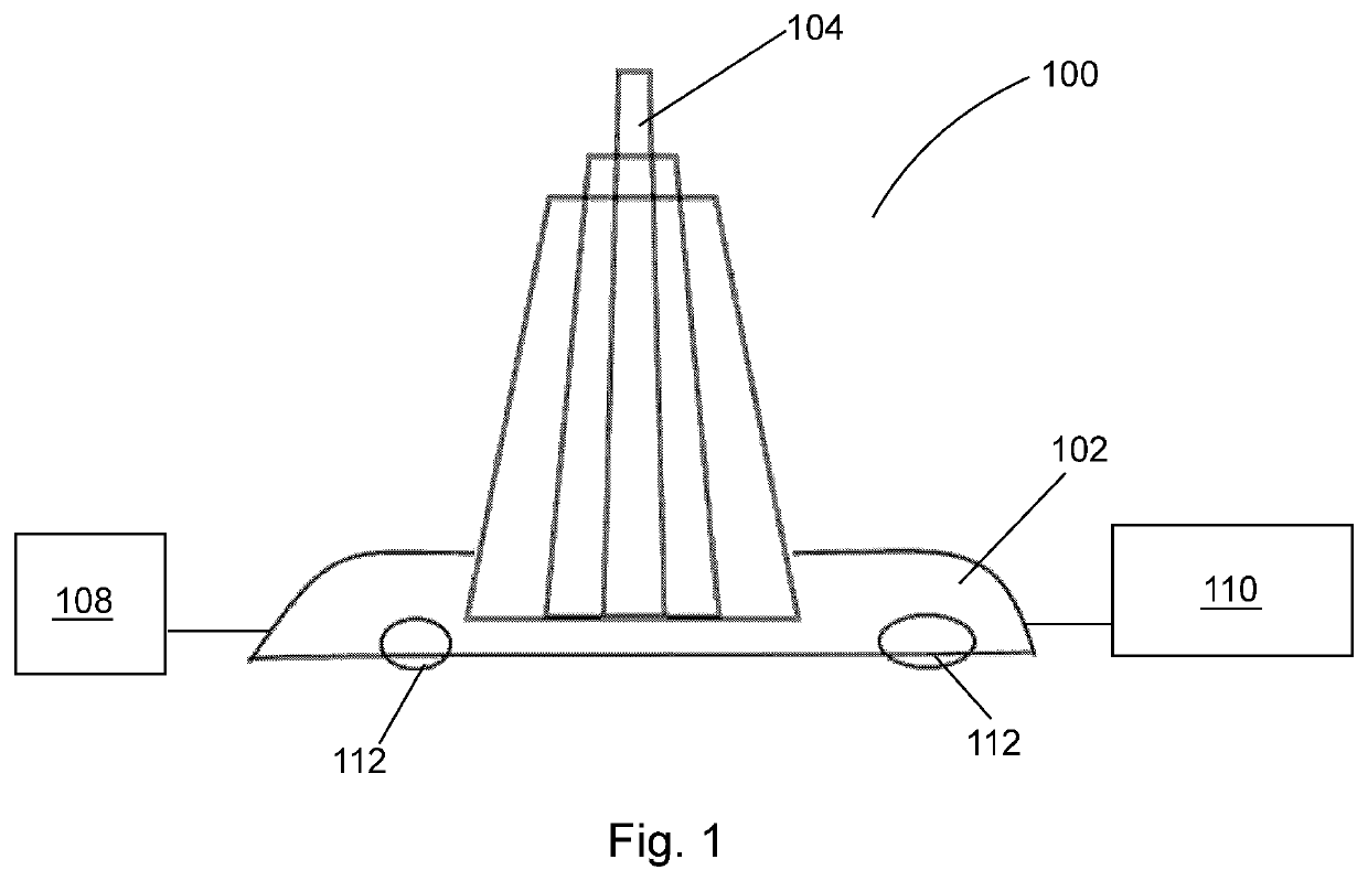
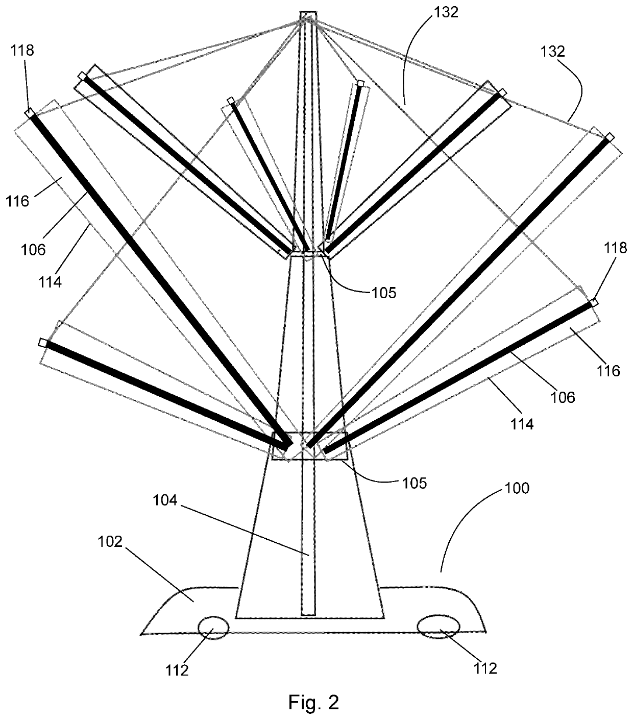
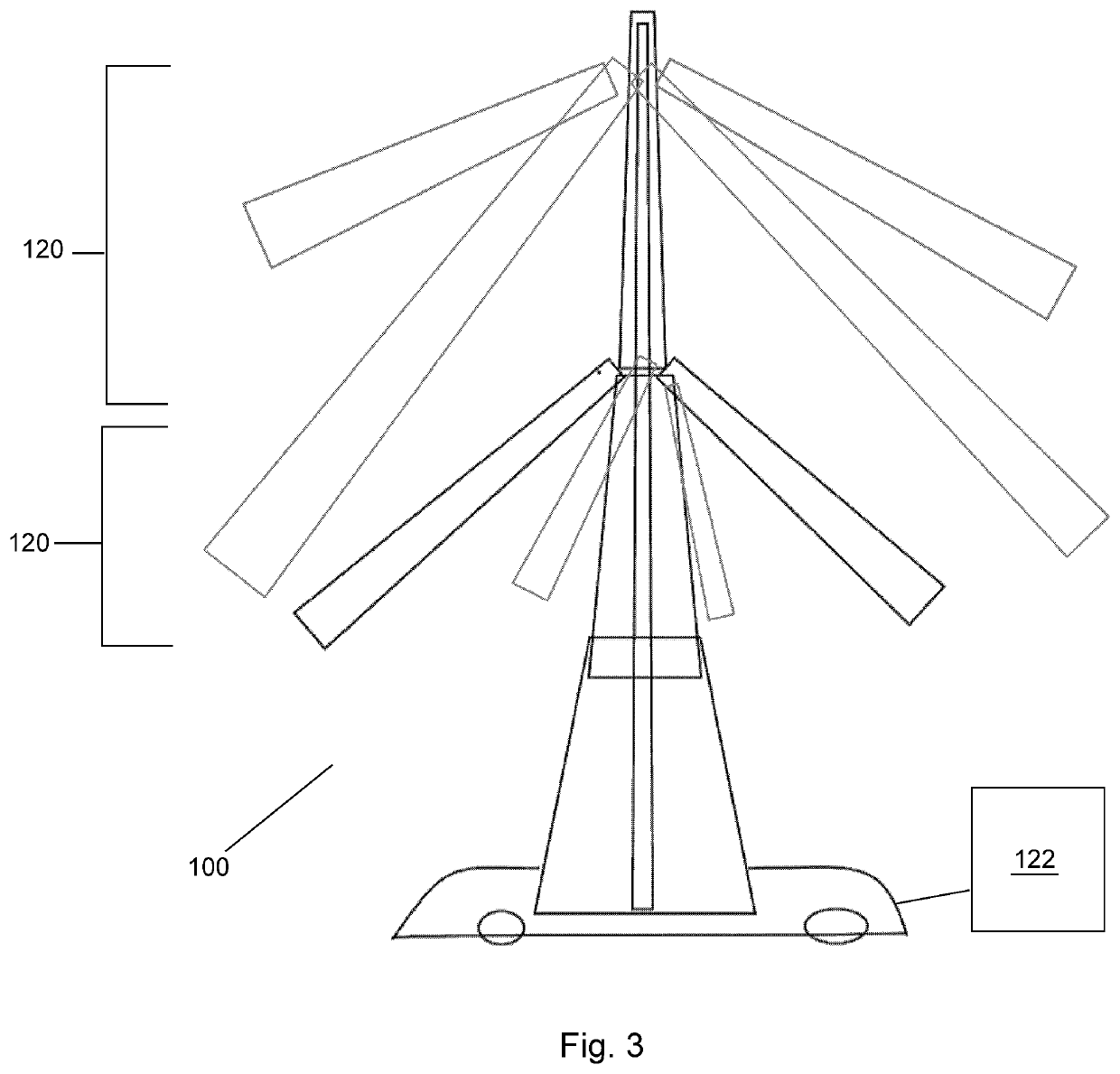
[0128]Referring to FIGS. 1 to 9, in accordance with one embodiment of the invention, a mobile solar tree 100 comprises a solar tree base 102 and a solar tree trunk 104 extending from the solar tree base 102. In one embodiment, the solar tree trunk 104 may extend substantially perpendicularly from the solar tree base 102. One or more solar tree branches 106 are connected to the solar tree trunk 104. Preferably, the solar tree branches 106 are hingedly or pivotably connected to the solar tree trunk 104 such that they may be actuated with respect to the solar tree trunk 104. In the embodiment shown in FIGS. 1 to 3, the solar tree trunk 104 comprises one or more horizontal bars 105 for attachment of the solar tree branches 106. For example, the solar tree branches 106 may be ...


PUM

PropertyMeasurementUnit
angleaaaaaaaaaa
angleaaaaaaaaaa
angleaaaaaaaaaa

Abstract

An apparatus for converting solar energy to electrical energy comprises at least a central trunk or stem, preferably extending from a base, wherein the base can be attached to a stationary structure like a wall or a house or a garage or a bridge or wherein the base can be part of a mobile device having wheels and at least one or exactly one branch and preferably multiple branches connected to the central trunk or stem, wherein at least or exactly a first branch comprises one or more photovoltaic panels. Additionally, or alternatively comprises a second branch one or more photovoltaic panels. Each of the photovoltaic panels of the first branch preferably comprises one or more sheets of photovoltaic material and preferably one or more anchors for attaching the sheets of photovoltaic material to the first branch.

Description

BACKGROUND OF THE INVENTION[0001]In a few years, many in the world will be switching to electric vehicles, and this will lead to a major and serious surge in the need and demand for electrical energy. In addition, California's new energy code mandates solar panels on roofs of all new building by 2020, which will have an effect on the design and aesthetics of buildings to a certain extent.[0002]Currently, solar farms are being built in an attempt to replace or supplement the power generated using conventional, traditional power stations, but these farms are also resulting in the destruction of trees and plants and most likely will negatively affect the environment and increase the amount of CO2 in the atmosphere. This will in turn lead to more desertification and may result in even bigger problems in the long run.[0003]Others have turned to floating solar farms as another option, but these have limitations and can only be deployed where water is present under the appropriate conditio...

Claims


Application Information

Patent Timeline
Patent Type & Authority Applications(United States)
IPC IPC(8): H02S30/20H02S10/12H02S20/26F03D9/00F03D9/32
CPCH02S30/20H02S10/12A62C37/40F03D9/007F03D9/32H02S20/26H02S20/30F03D9/34Y02B10/30A62C3/07A62C3/16Y02E10/728Y02E10/72Y02E10/50F05B2220/708F05B2240/94G01P15/18
Inventor PAULUS, ANTOINE MARCEL
Owner PAULUS ANTOINE MARCEL
Why Eureka
Try Eureka