Customizable helical telescoping internal craniofacial distractor

a technology of craniofacial distraction and telescopic articulation, which is applied in the field of customizable craniofacial distraction for craniofacial surgery, can solve the problems of warping the bones of the head into complex shapes that cannot be corrected, and the use of craniofacial distraction includes formidable challenges, so as to minimize the displacement/load of the condylar. , the effect of avoiding blood vessels, nerves and teeth

Pending Publication Date: 2022-03-31
THE METHODIST HOSPITAL
View PDF0 Cites 0 Cited by
  • Summary
  • Abstract
  • Description
  • Claims
  • Application Information

AI Technical Summary

Benefits of technology

[0010]The inner member of the steering apparatus may extend from a distal opening provided on the outer sleeve. Movement of the inner member and outer sleeve along the helical-shaped distraction path causes the inner member to further extend from the distal opening of the outer sleeve. The steering apparatus may further include an intermediate sleeve extending between the outer sleeve and the inner member, where the intermediate sleeve extends from a distal opening provided in the outer sleeve and the inner member extends from a distal opening provided in the intermediate sleeve. Movement of the steering apparatus along the distraction path will cause the intermediate sleeve to further extend from the distal opening of the outer sleeve and the inner member to further extend from the distal opening of the intermediate sleeve. The outer sleeve and the inner member may define a generally rectilinear cross-sectional shape. The outer sleeve and the inner member may also define a generally circular cross-sectional shape.
[0011]The anchoring member of the distraction device may include a first footplate for coupling the outer sleeve to the first bone segment and a second footplate for coupling the inner member to the second bone segment. The first and second footplates may be sized and shaped to correspond to a surface of the first and second bone segments, respectively. Each of the first and second footplates may also include an opening for receiving a bone screw to fix the first and second footplates to the first and second bone segments, respectively, where the location of each of the openings is predetermined to lay over a portion of the first and second bone segments having an increased thickness and avoiding a blood vessel, nerve, and tooth.
[0012]With respect to the present distraction device, at least one of the outer sleeve and inner member may be movable along the distraction path between a first position of the first and second bone segments and a second position of the first and second bone segments. The second position of the first and second bone segments may identify a predetermined re-aligned position of the first and second bone segments. The helical-shaped distraction path is the simplest path that will place the bone segments in the second (final) position. In the particular case of mandibular distraction, the helical-shaped distraction may be defined as the path of movement that minimizes condylar displacement / loading between the first and second bone segments during device activation, while realigning the bone segments into ideal position.

Problems solved by technology

However, compared with long bone distractors, the use of craniofacial distractors includes formidable challenges.
Unfortunately, rectilinear devices rarely produce good outcomes.
Craniofacial deformities warp the bones of the head into complex shapes that cannot be corrected without three-dimensional movements.
Unfortunately, the adjustments are limited and the devices are difficult to use.
Even if fully adjustable devices were available they can be impractical, for several reasons.
Fully adjustable devices tend to be very complicated and are difficult to miniaturize to a scale appropriate to the confines of the head.
Even if an appropriate fully-adjustable device can be made the correct scale, use of such devices would be burdensome and impractical requiring the operating surgeon to adjust six different knobs during distraction.
Moreover, experience with simpler adjustable devices shows that making mid-course adjustments is non-intuitive and fallible.

Method used


Image

  • Customizable helical telescoping internal craniofacial distractor
  • Customizable helical telescoping internal craniofacial distractor
  • Customizable helical telescoping internal craniofacial distractor

Examples


Embodiment Construction

[0078]The present invention may be understood more readily by reference to the following detailed description of preferred embodiments of the invention and the Examples included therein and to the Figures and their previous and following description.

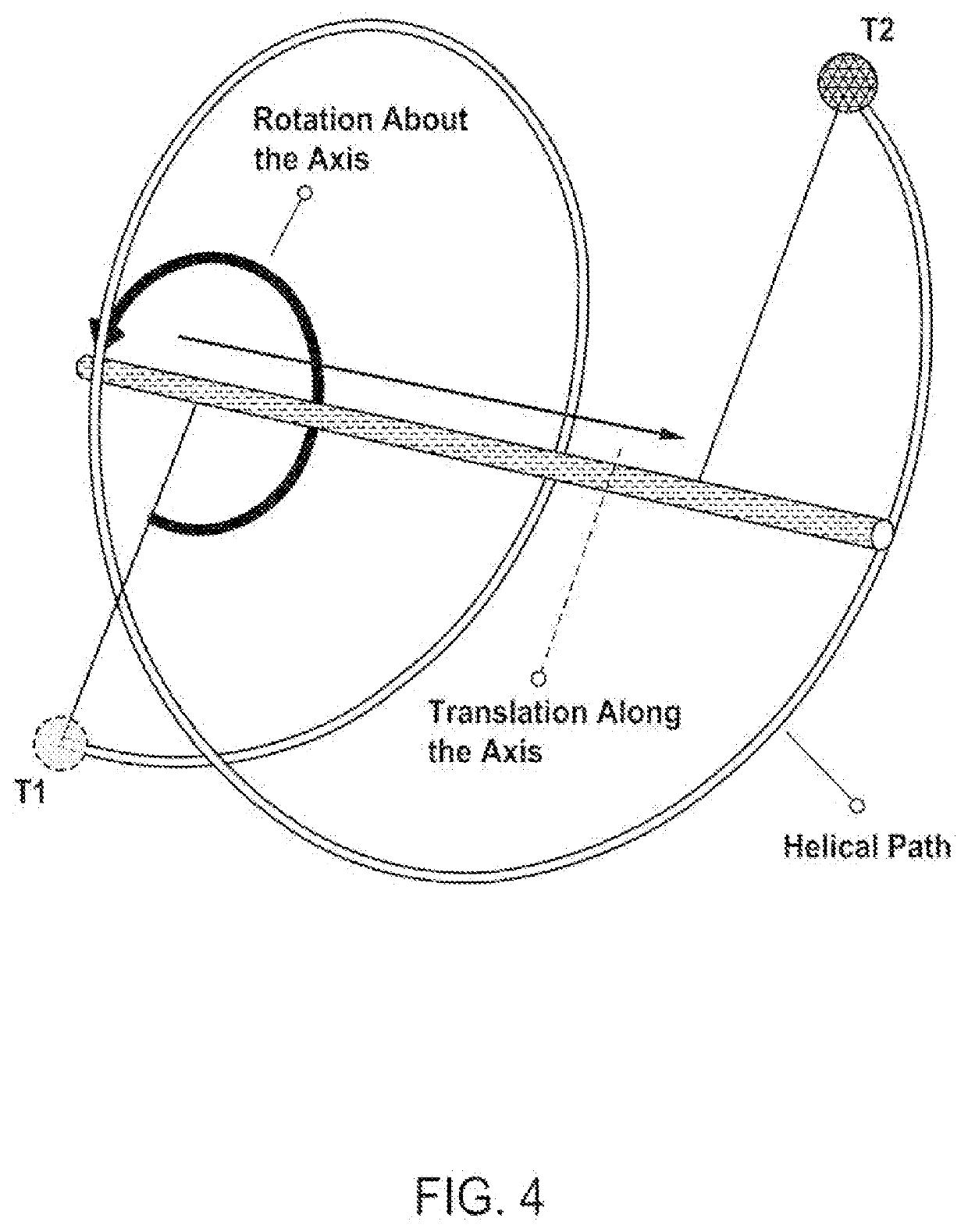
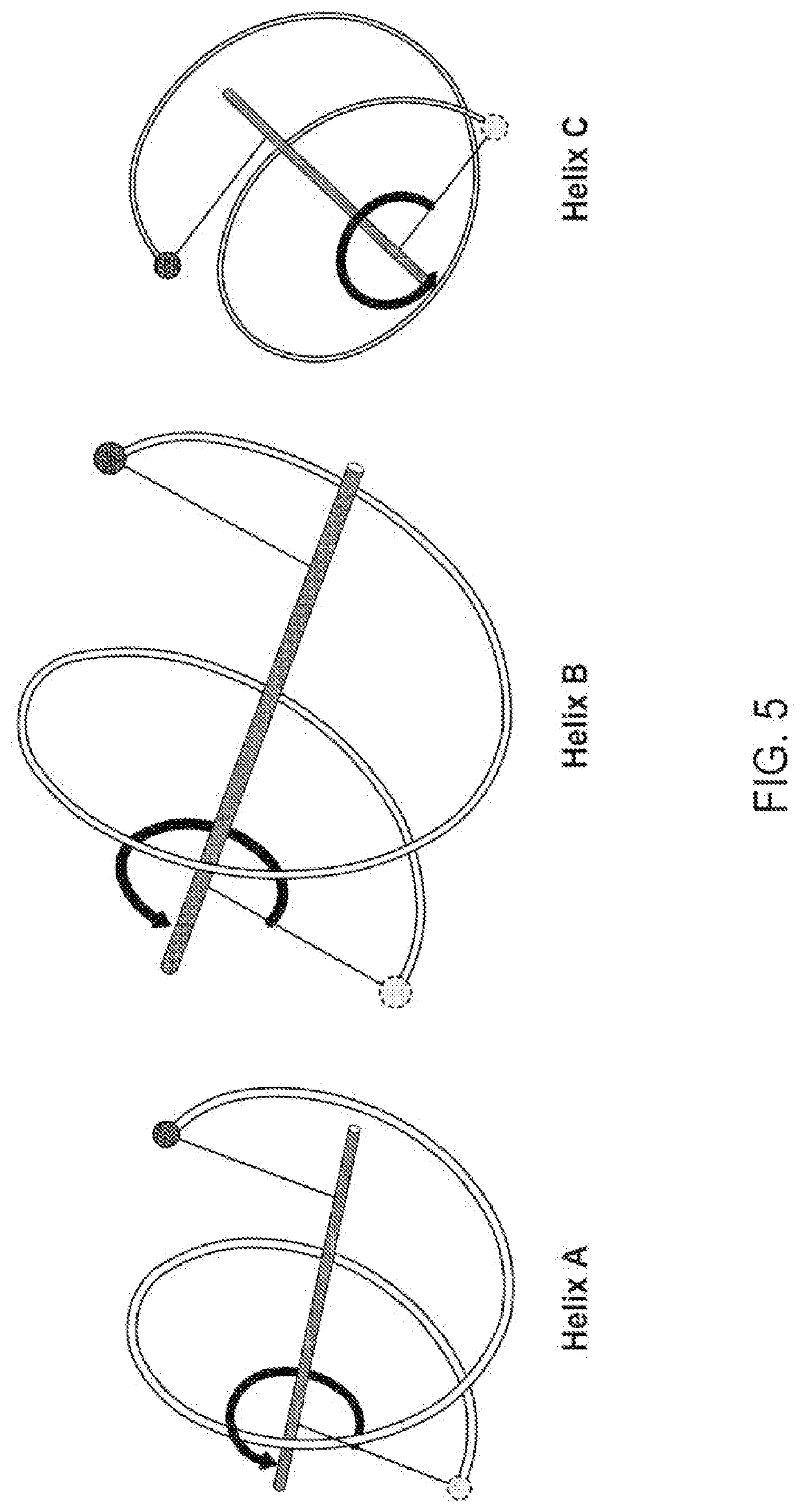
[0079]The present disclosure is directed to a craniofacial distractor that can move bone segments along a complex geometrical path that is customized and optimized for individual patients. The present distractor contemplates a nonadjustable device designed with a distraction path optimized for each patient, such that the distractor would only require activation. For each patient, an optimal distraction path is calculated, prior to surgery, and a custom device made. Though described in the context of use on a patient's face and cranium, it is contemplated that the present distractor can be used on any part of a patient's anatomy including, for example, the bones of the leg, arm, or torso.

[0080]Distraction devices must perform two distinct...


PUM


Abstract

The present disclosure is directed to a customizable distractor for oral and maxillofacial surgery and a system and method for designing and making the same. The distractor includes a steering apparatus that is movable along the helical-shaped distraction path to create gap between the first and second bone segments, an anchoring member for coupling the steering apparatus a first and second bone segment, and a distraction drive mechanism is used to drive movement of the steering apparatus along the distraction path.

Description

TECHNICAL FIELD[0001]This invention relates generally to a customizable distractor for craniofacial surgery.BACKGROUND OF THE INVENTION[0002]Distraction osteogenesis is a surgical technique for lengthening short bones to repair skeletal deformities and in reconstructive surgery. A distraction osteogenesis procedure begins with a surgeon cutting the deformed bone (osteotomy) and stabilizing the bone segments in their original position. The bone segments are stabilized in their original alignment with a special orthopedic device called distractor. The wound(s) are then allowed to heal and a soft bone-callous forms at the site of the osteotomy (latency). In an adult patient, this takes approximately one week, in a child it could take two to five days.[0003]In the next phase of distraction osteogenesis, the distractor is activated—periodically—to separate the bone segments, and to stretch the soft-callus (activation). Distraction is done slowly, over days or weeks, so that new bone will...

Claims


Application Information

Patent Timeline
Patent Type & Authority Applications(United States)
IPC IPC(8): A61B17/80A61B90/00A61B34/10
CPCA61B17/8019A61B17/8071A61B2017/00991A61B90/37A61B34/10A61B90/03A61B2017/568A61B17/663A61B2034/105A61B17/0206A61B2034/108A61B2034/254A61B17/8004A61B2090/035A61B2090/3762
Inventor GATENO, JAIME
Owner THE METHODIST HOSPITAL
Why Eureka
Try Eureka