Cooling device

Pending Publication Date: 2022-04-07
KAWASAKI HEAVY IND LTD
View PDF1 Cites 0 Cited by
  • Summary
  • Abstract
  • Description
  • Claims
  • Application Information

AI Technical Summary

Benefits of technology

The purpose of this patent is to provide a cooling device for a robot's heat-generating part that has a reduced number of components and does not have any components attached to the robot's arm.

Problems solved by technology

Further, since the passive radiator does not require electric power, wiring of an electric system becomes unnecessary, thereby increasing a degree of freedom in the layout of the radiator.

Method used


Image

  • Cooling device
  • Cooling device
  • Cooling device

Examples


modification 1

[0044][Modification 1 of Cooling Device 7]

[0045]Modification 1 of the cooling device 7 (7A) according to the above embodiment is described. FIG. 5 is a view illustrating a configuration of the cooling device 7 (7B) according to Modification 1. The cooling device 7 (7B) is comprised of the refrigerant circulation channel 70 (70A) of the cooling device 7 (7A) according to the above embodiment which is further provided with a second heat exchanging part 72.

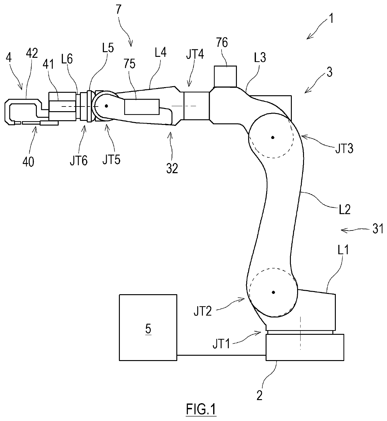
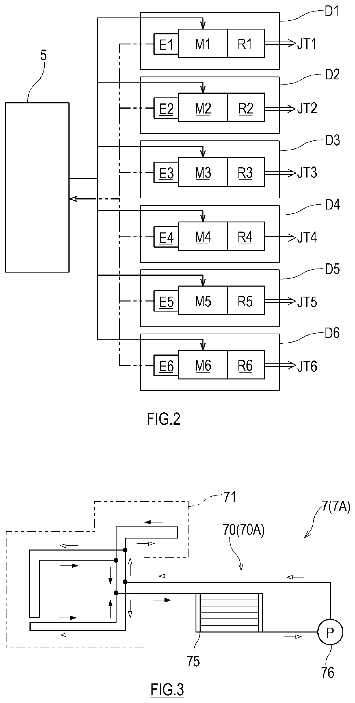
[0046]The heat generating part of the robot 1 includes the joint actuators D1-D6 which are heat generating parts of the arm 3. In more detail, the servomotors M and the reduction gears R included in the joint actuators D1-D6 correspond to the heat generating parts of the arm 3. A part of the refrigerant circulation channel 70 other than the first heat exchanging part 71, the radiator 75, and the pump 76, is formed as the second heat exchanging part 72 which exchanges heat between the joint actuators D1-D6 and the refrigerant.

[0047]Th...


PUM

PropertyMeasurementUnit
Flow rateaaaaaaaaaa

Abstract

A cooling device includes a refrigerant circulation channel, and a pump configured to pump refrigerant in the refrigerant circulation channel A heat generating part of an articulated robot includes a heat generating part of an end effector, and a part of the refrigerant circulation channel is formed as a first heat exchanging part configured to exchange heat between the heat generating part of the end effector and the refrigerant, and another part of the refrigerant circulation channel is formed as a radiator. The radiator is a passive radiator, and is attached in an exposed state to a part of the surface of an arm, configured to move in a space when a joint of the arm is driven.

Description

TECHNICAL FIELD[0001]The present disclosure relates to a cooling device which cools a heat generating part of an articulated robot.BACKGROUND ART[0002]Conventionally, a spot welding robot which automatically performs spot welding is known. Generally, the spot welding robot is an articulated robot in which a spot welding gun is attached to a tip-end part of an articulated arm Electrode tips of the spot welding gun become high temperature instantly. When the electrode tips melt, the weld performance of the electrode tips falls, and as a result, the weld efficiency falls. Therefore, the spot welding robot has a cooling device for cooling the spot welding gun including the electrode tips.[0003]For example, a spot welding robot disclosed in Patent Document 1 is provided in a robot body (i.e., an articulated arm) with a cooling device for cooling a spot welding gun. This cooling device includes a water storage tank, a water supply hose which supplies water inside the tank to the spot weld...

Claims


Application Information

Patent Timeline
IPC IPC(8): B23K11/30B23K11/31B23K11/36B25J19/00
CPCB23K11/3054B25J19/0054B23K11/36B23K11/315B23K11/314B23K37/003B23K11/11H05K7/20
Inventor KIDA, YASUAKINARIAI, HITOSHIFUKUHARA, KAZUMI
Owner KAWASAKI HEAVY IND LTD
Why Eureka
Try Eureka